IV. a - PRESTART CHECKS:
The compressor must float freely before connecting
to electrical power. The compressor motor is
provided with rubber vibration isolator mounts (no
springs). No bolts need to be loosened. Check all
exposed refrigeration lines to make sure they are not
dented or kinked. Check for tubing shifts due to
shipping that would cause operating noise, wear, or
leaks. Check that condenser fan rotates freely.
The refrigeration system should be checked for
proper operation before product is stored in the
cabinet.
IV. b - TEMPERATURE CONTROL:
The temperature is set at the factory but local
conditions may necessitate slight adjustment.
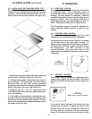
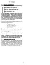
The temperature control shown in figure 11 is located
on the right side of the evaporator housing. To
adjust, turn the adjustment screw with a screwdriver
a small amount at a time; turning clockwise lowers
the temperature. An "OFF" position is fully
counterclockwise and interrupts power to the
compressor and condenser fan only, not the entire
refrigerator.
IV. c - DEFROST CONTROL:
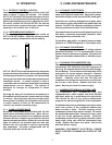
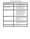
Frozen food storage cabinets are equipped with a
defrost timer (figure 12) that provides a 20-minute
defrost cycle every 6 hours (four defrost cycles per
day).
This control can be adjusted to set when the next
defrost cycle will start. To adjust the defrost time
control, use a coin on the outside slot in the rim of
the timer and turn clockwise until the compressor
turns off. Continue turning coin clockwise until the
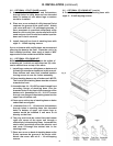
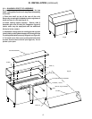
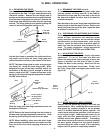
III. l - INSTALLING THE STAINLESS STEEL TOP:
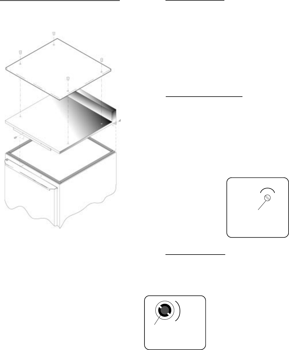
All 27", 48" and 60" wide compact undercounter
models can be supplied with an optional stainless
steel top. This must be installed on-site, to do so
please follow the directions below (see figure 10):
1. Peel off backing and install foam tape (provided)
around entire perimeter of the top of the unit.
2. A flange is assembled underneath at the front of
the countertop. This flange has two screw holes.
Screw the two 1/4 – 20 x 5/8" screws (provided)
through the holes in this front flange into the threaded
holes in the front of the top edge of the unit.
3. Using the five 10 – 16 x 1/2" screws provided,
screw the bottom of the rear cover plate to the upper
rear of the cabinet.
4. If the optional polyethylene cutting board top is
provided, there are four threaded pins which screw
into the four threaded holes in the worktop. The four
holes in the polyethylene cutting board top fit around
the heads of the four pins.
-6-
III. INSTALLATION (continued)
IV. OPERATION
Fig. 10
Fig. 11
Thermostat - All
Current Models
Fig. 12
Defrost Timer
Models ULT27, ULT48 & ULT60 Only
▼
Clockwise
Rotation
Only
Defrost
Time
Control
F
R
O
N
T
⇐
▼
Temperature
Adjustment
Screw
Colder


