19
ELECTRICAL CONNECTIONS
Important
Any electrical work required to install
this cooker should be carried out by a
qualified electrician or competent person, in
accordance with the current regulations.
THIS COOKER MUST BE EARTHED
The manufacturer declines any liability
should these safety measures not be
observed.
This cooker is designed to be connected to a
240V, 50Hz electrical supply.
To connect to the electricity supply, use cable
type H05 RR-F.
Before connection, make sure the electricity
supply voltage is the same as that indicated on
the rating plate.
The cooker is supplied without supply cable. A 3
core flexible supply cord must be fitted, in
accordance with the specification given in the
table no.1.
The electrical connection should be made using
a double pole isolating switch (cooker control
switch) with at least 3mm contact separation in
all poles. The cable must have conductors of
sufficiently high cross-sectional area to prevent
overheating or deterioration.
The switch should be sited within 2m of the
cooker and be easily accessible at all times.
The yellow-green earth wire must not to be
interrupted by the switch.
Ensure that the cooker supply cable
does not come into contact with surfaces
with temperatures higher than 50 °C.
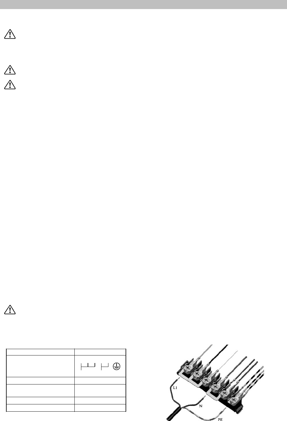
Table no.1
Connection type Single phase (UK)
Cable connection to the
terminal block
1 2 3 4 5
L1
N PE
Mains Voltage
240 V
Voltage of heating
elements
240 V
Fuse capacity
32 A
Cable section
3x6 mm
2
NOTE: The earth wire should be about 2 cm
longer than the live and neutral wires.
Before connecting check that:
• The fuse and household electrical installation
can carry the absorbed current of the
appliance (see rating plate);
• The cooker connection outlet or the cooker
control switch is easily accessible when the
appliance is installed.
How to proceed?
• Unscrew and remove the protective cover at
the back of the appliance;
• Connect the power cable to the terminal
block of the cooker according to the table
no.1;
• Secure by means of cable clamp;
• Make sure that the connection to the terminal
block is matching the supply system, see
table no.1;
• Refit and screw the protective cover on the
back of the appliance.


