............ www.truemfg.com ............
True Food Service Equipment, Inc.
6 6
INSTALLATION / OPERATION INSTRUCTIONS
Step 4
NOTE
Hard wiring is required on standard "Dry" Bakery
Cases.
NOTE
Optional 12" (30.5 cm) corded model available, fac-
tory installed only. (exterior scale receptacle will not
be included with this option.
A. Before your new unit is connected to a power
supply, check the incoming voltage with a volt-
meter. If anything less than 100% of the rated
voltage for operation is noted, correct immedi-
ately.
Refer to cabinet data plate for voltage.
True requires that a sole use circuit be dedicated
for the unit.
WARNING
If your bakery case includes optional 12" (30 cm)
power supply cord, ground should not be removed!
NOTE
To reference wiring diagram - wiring diagram is
positioned on the ballast box inside lower rear of the
cabinet.
ELECTRICAL INSTRUCTIONS
Step 5
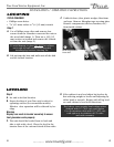
A. Verify that the cabinet lights are working.
Bakery cases are shipped with light switches in
the "on" position. The toggle switch is located
lower right corer at the rear.
REPLACEMENT PARTS
TRUE maintains a record of the cabinet serial number
for your unit. If at any time during the life of your dis-
play case, a part is needed, you may obtain this part
by furnishing the model number and serial number
to the company from whom you purchased the cabi-
net. Call Toll-Free: (800)-424-TRUE (Direct to Parts
Department). (800)-325-6152 (U.S.A. & Canada only)
or call: (636)-240-2400.
STARTUP
NON-REFRIGERATED "DRY" CURVED
GLASS DISPLAY CASES
(hard wired models only)
Hard wired Bakery Cases are equipped
with a service receptacle (found on the
upper right cabinet backside). No elec-
trical load greater than 4.0 amps should
be connected to it.


