


Page 17
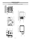
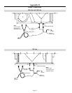
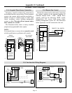
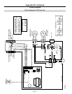
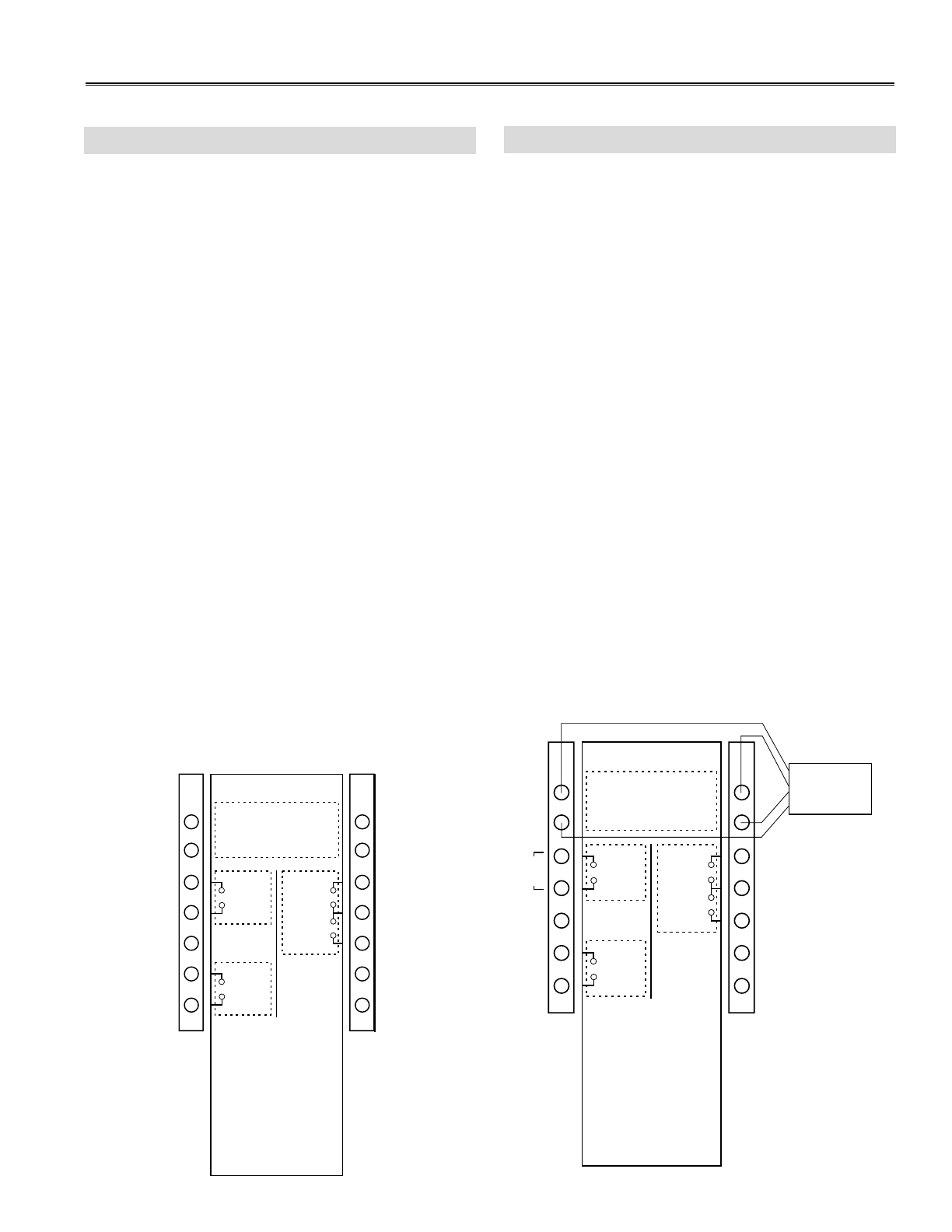
WALL CONTROL
CLASS 2 VOLTAGE
Black
OCCUPIED
TIMER/
SENSOR
F
F
LOW
COMMON
HIGH
Red
Green
Yellow
NOTE:
Connections are all dry
contacts except wall control
and 24VAC power supply.
Use of 24VAC circuit
requires isolating contacts
(ex. thermostat) to prevent
interconnection of Class 2
outputs.
VE0002A
Wall
Control
JUMPER
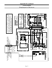
WALL CONTROL
CLASS 2 VOLTAGE
Black
OCCUPIED
TIMER/
SENSOR
F
F
LOW
COMMON
HIGH
Red
Green
Yellow
NOTE:
Connections are all dry
contacts except wall control
and 24VAC power supply.
Use of 24VAC circuit
requires isolating contacts
(ex. thermostat) to prevent
interconnection of Class 2
outputs.
VE0006A
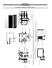
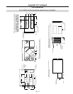
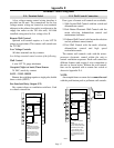
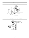
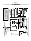
A low voltage remote control wiring interface is
provided on the unit. The connections for the low
voltage remote wiring are located on two terminals
adjacent to the exhaust fan outlet (or adjacent to the
supply fan outlet on the 700 cfm unit). All field
installed wiring must be low voltage class II.
Remote Wall Control
Optional wall control requires a 4 wire LVT-24
gauge (or equivalent). This remote wall control runs
on 12 VDC.
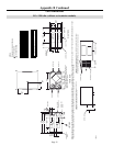
Low Voltage Controls
All other terminals are dry contacts.
Low Voltage terminal control consists of the following:
Wall Control
4 wire LVT 24 gauge minimum
Occupied (Night set back) Timer/Sensor
24 VAC, needs dry contact
LOW - COM - HIGH
Remote fan switching requires a single pole, double
throw switch (SPDT)
Fan Interlock Relay Output (FF)
Dry contact closes on ventilation or defrost. Used
to control external fan.
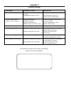
Four types of remote wall controls are available:
1. Slide Switch Wall Control with fan switch and
dehumidistat control
2. Push Button Electronic Wall Control with fan
mode selection, dehumidistat control and
maintenance indicator
3. Pollutant Wall Control with fan mode selection
and air pollutant sensor/control
4. Pool Wall Control with fan mode selection,
dehumidistat control and high speed
recirculation mode.
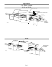
The remote wall controls work with the micro-
processor electronic control within the unit to
control ventilation sequences. Each wall control has
different features and require 4-wire connection to
the unit as shown below. Without the wall control,
fans can be operated with a remote fan switch as
shown in Appendix E-4.
NOTE:
An occupied timer or sensor device cannot be used
with the push button pool or pollutant wall controls.
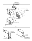
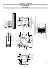
Appendix E
Terminal Control Diagrams
E-1: Terminal Label
E-2: Wall Control Connection