


Page 5
2.8 Electrical Connections
Power
A terminal block and strain relief bushing or a
junction box is provided for line voltage to make the
necessary power connections.
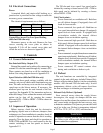
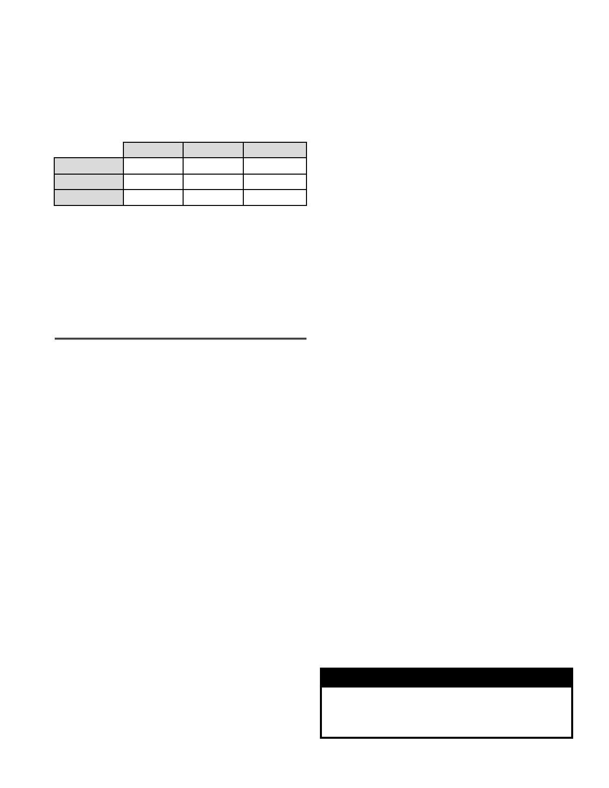
The electrical requirements are as follows:
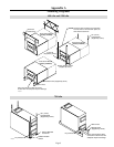
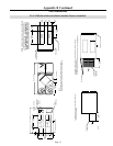
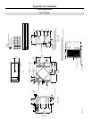
Control Box Access For Low Speed Setting
(600 cfm/1200 cfm only)
Disconnect power to the unit. Remove the four
screws securing the cover plate as shown in
Appendix F. Lift off the control cover plate and
switch the red wire as shown in Appendix F.
3 Controls
3.1 General Information
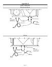
Fan Interlock Relay Output (FF)
External fan control can be achieved by connecting an
external 24 volts fan control through dry contacts (FF).
These contacts are closed on a call for ventilation or
defrost. See wiring diagram shown in Appendix E-5.
Speed Selection (600 cfm/1200 cfm only)
There are three speed settings available with the
controls, only two of which can be functional at any one
time. The units are factory set to use the low and high
speed taps on the blower motors. If necessary, the
medium speed tap can be used instead of the low
speed tap. See Appendix E-2 for instructions on how to
make this change. Units without the remote wall control
option can be shut off by opening the contact
between LOW - COM or HIGH - COM as shown in
Appendix E-2.
3.2 Sequence of Operation
Before start-up, check the unit for obstructive
packaging, objects near or in blowers, dampers, heat
exchangers, etc. Once installation is complete, check all
modes of operation to ensure that the unit is working
properly. Close the doors and check for operation on
LOW, COM and HIGH. Use a wall control or the dry
contact switching to run fan speeds as shown in
Appendix E-2.
The 700 cfm unit is two speed. Low speed can be
initiated by creating a closure across LOW - COM or
high speed can be initiated by creating a closure
across HIGH - COM.
Unit Check points:
___ Power connected, no ventilation call - Both fans
are off, defrost damper (if equipped) closes off
fresh air from outside.
___ Power connected, low speed call - Both fans on
low speed internal defrost damper (if equipped)
opens fresh air from outside. If equipped with
recirculation module, the internal defrost
damper closes recirculation opening.
___ Power connected, high speed call - Both fans on
high speed, defrost damper opens fresh air from
outside. If equipped with recirculation module,
the internal defrost damper closes recirculation
opening.
___ Power connected, occupied timer/sensor connection
open (unoccupied mode) - Both fans are off, defrost
damper closes fresh air from outside. If equipped
with recirculation module, the internal defrost
damper opens recirculation opening.
___ Power connected, FF control contacts close
during unit ventilation or defrost cycle.
3.3 Defrost
The unit functions are controlled by integrated
controls in the unit which may include Exhaust Only
Defrost or Recirculation Defrost (via the recirculation
module - 600 cfm and 1200 cfm units only). In cold
temperatures, defrost cycles will remove frost from
the heat exchanger to maintain good operation.
Exhaust Only Defrost (Optional)
Frost removal occurs when the supply blower
de-energizes, the supply air damper and the core
damper close and the exhaust fan continues to circulate
only warm inside air through the heat recovery core
to maintain ventilation. This process prevents the build
up of ice in the core. Defrost is temperature initiated
at 23°F to -22°F (-5°C to -30°C) and time based.
VOLTAGE 115V 115V 115V
MCA 8.65 6.63 13.4
MOP 12.5 9.13 20
600 cfm 700 cfm 1200 cfm
WARNING
A negative building pressure may develop during
the defrost cycle with possible backdrafting fumes
from combustion equipment.