


Page 8
Allow the heat recovery core to soak for three
hours in warm water and mild soap. Rinse under a
heavy stream of water.
Fans
Blower wheels and fan housing should be checked
for dirt build-up. If they appear dirty, it may be
necessary to remove the blower assembly and then
vacuum the dust out through the fan mouth. See the
following page for instructions on removing the
blower assembly.
System Operation Check
Verification of all control modes should be
checked to ensure proper operation. Refer to the
Controls Section, Sequence of Operation.
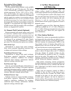
Testing and Replacement of the Damper Actuator
Check damper operation by switching between
LOW - COM or HIGH - COM on the dry contact
terminal or by switching through the modes on the
optional remote wall control. If the damper does not
respond in one or both directions, check all connections.
700 cfm ONLY: Check for 24 volt output between the
White/Red and the White/Orange wires at the damper
motor. If 24 volts can be measured at the damper
motor, the problem is either in the connections, the
defrost relay or the main circuit board.
600/1200 cfm ONLY: (CAUTION: 120VAC) Check
for 120 volt output across the White/Black wires. If
120 volt can be measured at the motor, replace the
motor. If 120 volt cannot be measured at the motor,
check pins J1-9 at the printed circuit board.
Main Circuit Board Replacement
The main circuit board must be replaced if an
electronic problem arises. For example, the unit
suddenly stops, the unit stays in defrost all of the
time or if control functions are not working properly.
Ensure that power is reaching the board. Test the
blower motors and damper actuators for operation
when directly connected to the appropriate power
voltage. If the motor and damper actuators function
normally, replace the main circuit board.
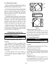
Motor and Blower Removal and Installation
Disconnect power from the unit. To determine if
the fan motor is burned out, disconnect the four-wire
service connector between the motor and cabinet.
Connect the motor directly to a 115 volt power
source with an electrical cable, as follows:
If the motor functions normally, there is a problem
with the wiring connections or the main circuit
board. Check all wiring and replace main circuit
board if necessary.
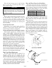
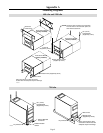
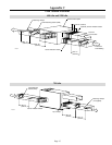
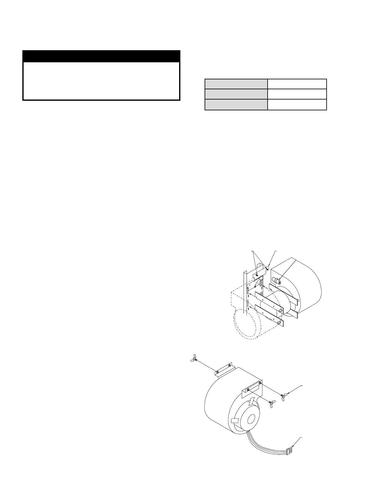
If the blower does not run, it must be replaced. To
replace the motor, remove the heat recovery core
from the unit. Disconnect the four-wire service connector
from the unit. Remove the fasteners holding the
motor assembly in place. Lift the assembly up and
out, using one hand under the motor and one hand to
steady it. Remove the assembly carefully from the
unit to avoid damage to the insulation, shelf, etc.
Install the repaired motor assembly by following
these instructions in reverse.
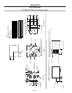
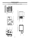
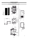
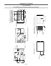
600 cfm and 1200 cfm
700 cfm
RED + WHITE Low speed
BLUE + WHITE Medium speed
BLACK + WHITE High speed
REMOVE THESE
2 SCREWS
LOCKING PLATE
CAPACITOR
VD0004A
SERVICE CONNECTOR
THUMBSCREW
VD0001A
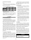
WARNING
Hot water and a strong cleaning agent could
damage the polypropylene core. Ensure the core is
returned to the unit in the correct orientation. Use
the sticker as a guide.