


1716
1
Me
a
sur
ement
(
A
)
Measurement (A)M
e
a
su
r
ement
(
A
)
2
M
eas
ur
e
m
en
t
(
A)
Measurement (A)
+1
/
2”
+1/2”
(1.3
c
m
)
(1.3 cm)
M
eas
ur
e
m
en
t
(
A)
+1
/
2”
(1
.
3
c
m
)
3-
5
/8”
3-5/8”
(9
.
2
c
m)
(9.2 cm)
3-
5
/8”
(9
.
2
c
m)
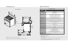
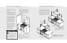
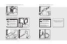
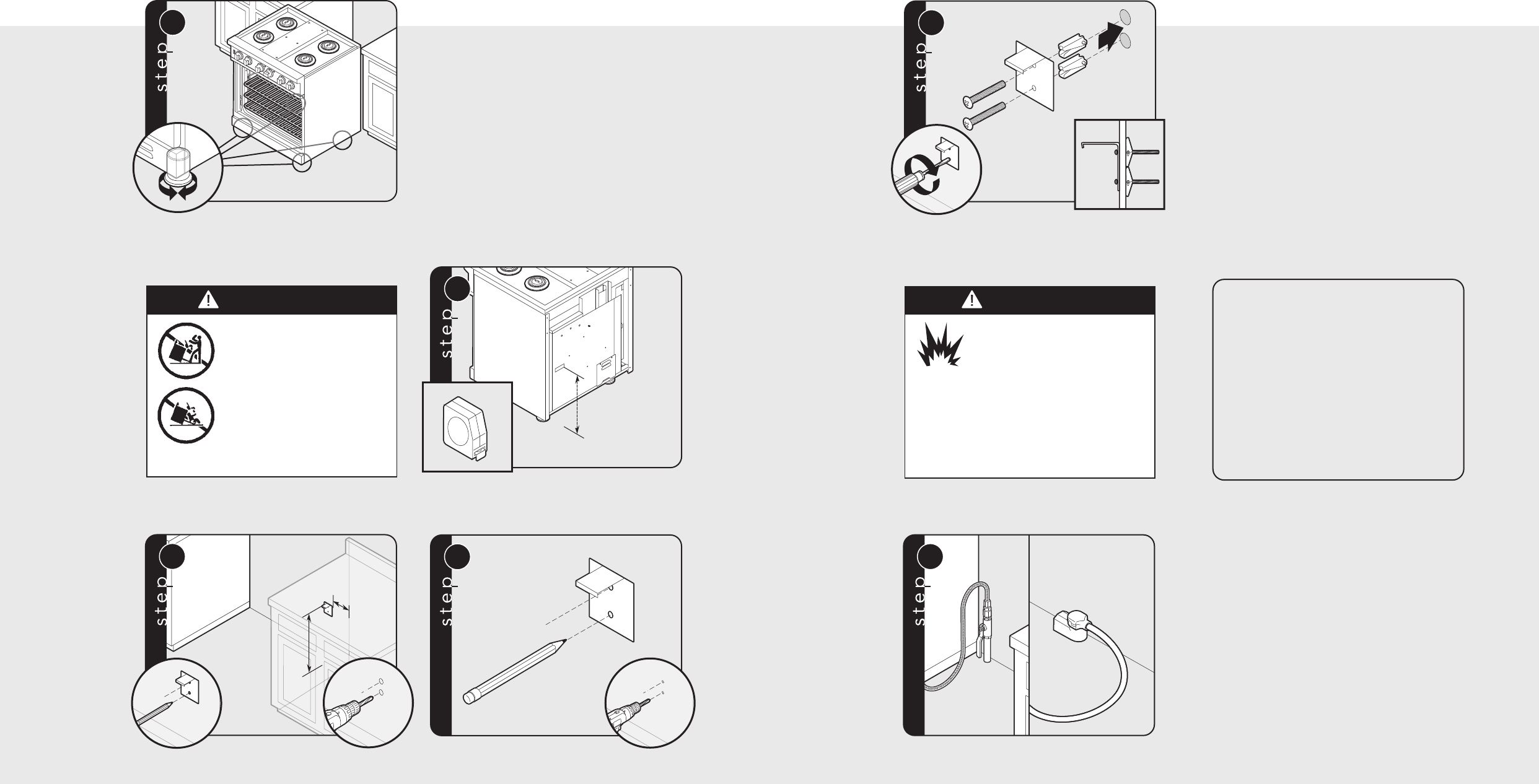
Measure from floor to bottom
of the anit-tip opening located on the back of range.
This will be measurement (A).
Locate anti-tip bracket on rear wall with the top left corner at
measurement (A) plus 1/2” (1.3 cm) from the floor and 3-5/8” (9.2 cm)
from where the right side of range (facing range) is to be located.
1
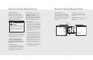
Note: Refer to electrical and gas
requirements section for proper
installation information.
3
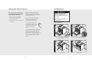
Mark and drill holes where bracket will be located.
4
Attach bracket with
mounting hardware provided.
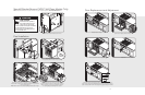
Connect gas and electrical. Before placing appliance in operation,
always check for gas leaks. This must be performed by your
dealer, a qualified licensed plumber, or gas service company.
Leveling/Adjustments/Alignments (cont.)
Connecting Gas & Electric
WARNING
TIPPING HAZARD
To reduce the risk of property
damage or personal injury;
install anti-tipping device
provided in accordance with
the installation instructions
in this document. Device
must be engaged properly to
prevent product from tipping
over.
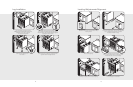
7
Set the high corner of range so that the top of side trim is
3/8” (0.95 cm) above countertop. Level range to high corner.
DANGER
GAS LEAK HAZARD
To avoid risk of personal injury
or death; leak testing of the
appliance must be conducted
according to the manufacturer’s
instructions. Before placing appliance in
operation, always check for gas leaks
with soapy water solution.
• DO NOT USE AN OPEN FLAME TO
CHECK FOR GAS LEAKS.
Anti-tip Device Installation
Anti-tip Device Installation
(cont.)