


29
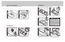
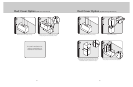
CAUTION: If not using a duct cover, using screws
provided, make sure top mounting screws are secured
into soffit or cabinet framing. Use additional mounting
screws, if necessary.
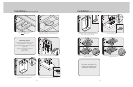
Connect black to black, white to white, and the
green/bare wire under the green screw.
NOTE: Housing wiring must be properly installed for
wiring to be correct when wiring unit.
5/16”
n
ut driver
BLACK
BLACK
WHITE
WHITE
GREEN
BARE OR GREEN
7
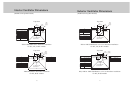
Replace electrical box cover. Make connection to
breaker box.
1
1
2
8
Slide filter front over front lip. Push filter rear up, then
slide back over rear lip.
1
2
1
3
9
CAUTION: Secure vent hood to wall using screws
provided. Use additional mounting screws and wall
anchors, if necessary.
6
5/16”
n
ut driver
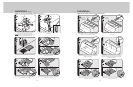
28
1
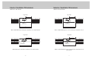
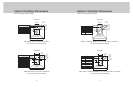
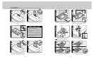
Check damper for unrestricted movement, adjust if
necessary.
2
3
Attach transition to damper. Seal with aluminum tape.
Flip hood over and remove electrical box cover.
1
4
2
1
5
Insert 6” of electrical wiring through the top of vent hood
and secure using wiring restrain. Refer to local codes.
Slide duct over transition and tape around joint.
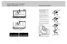
WARNING
To reduce the risk of fire, electric shock, or injury
to persons, observe the following:
• Use this unit only in the manner intended by the
manufacturer. If you have any questions, contact
the manufacturer.
• Before servicing or cleaning unit, switch power off
at service panel and lock service panel to prevent
power from being switched on accidentally. When
the service disconnecting means cannot be locked,
securely fasten a prominent warning device, such
as a tag, to the service panel.
1
2
3
10
Slide filter front over front lip. Push filter rear up, then
slide back over rear lip.
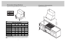
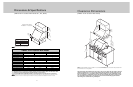
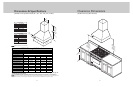
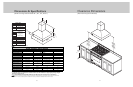
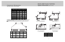
Installation (VWH 10” H./12”H. Wall Hoods w/Standard Ventilator)