


PLANNING AND DESIGN GUIDE
VIKINGRANGE.COM • 1-888-VIKING1
COOKING
Professional Built-In Electric Induction
30”/36”W. Cooktop
H
O
T
R
E
A
R
F
R
O
N
T
H
O
T
R
E
A
R
F
R
O
N
T
3
6
”
m
i
n
.
(9
1
.4
c
m)
1
3
”
m
a
x
.
(
3
3
.0
c
m
)
6
”
m
i
n
.
(
1
5
.
2
c
m
)
1
8
”
m
i
n
.
(
4
5
.
7
c
m
)
3
-
1
/
8
”
(
7
.
9
c
m
)
0
”
m
i
n
.
(
0
.
0
c
m
)
*
3
6
”
m
i
n
.
(
9
1
.
4
c
m
)
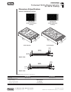
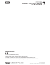
• Below countertop 3-1/4” (8.3 cm)
minimum
• Above countertop 36” (91.4 cm)
minimum
• Side 6” (15.2 cm)
• Rear* 0” minimum
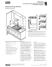
• Within 6” side clearance. Wall
cabinets no deeper than 13” (33.0 cm)
• Center of cutout from rear wall/back
splash minimum 10-1/2” (26.7 cm)
• Countertop depth 25” (63.5 cm)
• Cabinet depth from rear maximum
13” (33.0 cm)
• Cabinet height from countertop
minimum 18” (45.7 cm)
1. The cooktop CANNOT be installed
directly adjacent to sidewalls, tall
cabinets or appliances, or other side
vertical surfaces above 36” (91.4 cm)
high. A minimum side clearance of 6”
(15.2 cm) is required between the
cooktop and such combustible
surfaces above the counter.
2. A minimum height clearance of 18”
(45.7 cm) is required between the
countertop and wall cabinets no
deeper than 13” (33.0 cm) above the
countertop.
3. These dimensions are based on a
standard 24” (60.1 cm) deep base
cabinet with a 25” (63.5 cm) deep
countertop and 3/4” backsplash.
4. If a ventilation hood is installed over
the cooktop, the minimum 36” (91.4
cm) height clearance above the unit
does not apply. Refer to the hood
installation instructions for further
information.
Warning
The use of cabinets for storage above
the appliance may result in a potential
burn hazard. If a cabinet storage is to be
provided the risk can be reduced by
installing a hood that projects
horizontally a minimum of 5” (12.7 cm)
beyond the bottom of the cabinets.
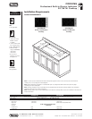
Important: To ensure proper
performance and extend the life of the
electric components in the cooktop, it is
required that a minimum height
clearance of 1-1/2” (3.8 cm) be located
between the bottom of the induction
cooktop and any shelf or combustible
surface directly below the cooktop. This
includes the top edges of drawers
located directly beneath the cooktop. If
a shelf or drawer is located directly
below the cooktop, a 1” (0.4 cm) gap at
the front of the shelf or drawer is
necessary to allow for proper ventilation.
Dimensions & Specifications
CLEARANCE DIMENSIONS
Minimum clearances from adjacent combustible construction
18”
(45.7 cm) max.
1-1/2”
(
3.8cm)min.
Interior Cabinet Clearances
IMPORTANT: The electronic components for the induction
elements in the cooktop need air circulation. To ensure
long life of electronic components, it is required that 1-1/2
(3.8 cm) or more open space remains between the bottom
of the cooktop and any shelf underneath. The maximum
length of the shelf underneath is 18” (45.7 cm). It is
required that the exit air ports at the front are not blocked.
RELEASED 10/10/08
©2008 VRC—INFORMATION SUBJECT TO CHANGE
Hot Air
Hot Air
Hot Air
G
ood Design
O
ptimum Design
Bad Design
Cool Air
Cool Air
C
ool Air