


6
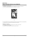
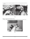
TRANSFORMER CHECK
1. Follow steps 1-3 under Accessing of Controls Inside the Control Box.
2. Follow Steps 1-4 under Removal of Transformer.
3. With a volt meter and the appliance "on", check the voltage across the load and line terminals. Voltage
should match that of the transformer markings.
EXAMPLE: Transformer marked - PRI. 120V
SEC. 24VAC
Means that the load input reading should be 120V and the line output reading should be 24V.
4. If the readings do not match replace the transformer.
5. If readings do match but transformer problem is still suspected, check for resistance across the load terminal
and the line terminal with an ohm meter. If there is no resistance at either end of the lines
replace the transformer.
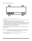
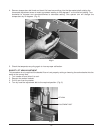
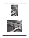
BASKET LIFT RELAY
1. Follow steps 1-6 under Removal of Basket Lift Back.
2. With power "on" using an ohm meter check for 0 ohms between connections 5 & 3 and also between 6 & 4.
3. With power "off" using an ohm meter check for a coil resistances of above 168 ohms. Also check for
continuity of 0 ohms between connections 1 & 5 and 0 & 6.
4. If any of the above checks do not prove out replace the relay.
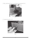
BASKET LIFT MICRO SWITCH
1. Follow steps 1-6 under Removal of Basket Lift Back.
2. Remove switch wiring. Engage the switch and with an ohm meter check for continuity across the common
and normally open circuits. If continuity is not shown replace the switch.
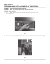
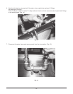
BASKET LIFT MOTOR
1. Follow steps 1-6 under Removal of Basket Lift Back.
2. Follow steps 1-7 under Removal of Basket Lift Motor.
3. With volt meter and power on check for voltage to the motor.
4. Verify that the motor voltage agrees with the voltage as stated on the appliance rating plate.
5. Check the motor wire connections.
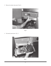
6. Disconnect power and disconnect the motor wires at the motor terminals.
7. With ohm meter measure the resistance across the terminals. The resistance should be about 28 ohms.
8. If resistance is not correct replace the motor unit.
BASKET LIFT TIMER
1. Follow steps 1-4 under Removal of Cooker Panel.
2. Check for good wire connection at the terminals.
3. Push power switch "on".
4. With a volt meter check for 24Vac across the input terminals of L1 and L2.
5. With a volt meter check for 24Vac across the load terminals after pushing the timer button and
setting the timer. Reading should remain constant at 24vac until the timer runs out.
6. If the above readings are not achieved replace timer.