


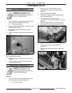
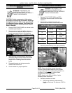
MODEL C24EA - HEATING ELEMENT
F25213 (May 2006)Page 19 of 52
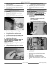
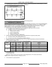
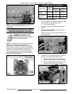
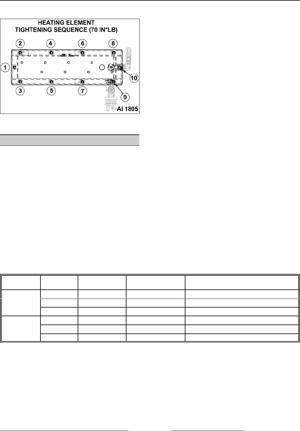
9. Reassemble parts removed in reverse order of removal. Tighten heating element screws evenly to 70 in*lbs.
Follow tightening sequence pattern as shown in illustration.
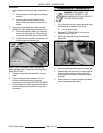
10. Check steamer for proper operation and leaks around heating element.
DIAGNOSTIC CHECKS
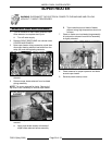
WARNING: CERTAIN PROCEDURES IN THIS SECTION REQUIRE ELECTRICAL TEST OR MEASUREMENTS
WHILE POWER IS APPLIED TO THE MACHINE. EXERCISE EXTREME CAUTION AT ALL TIMES. IF TEST
POINTS ARE NOT EASILY ACCESSIBLE, DISCONNECT POWER AND FOLLOW LOCKOUT / TAGOUT
PROCEDURES, ATTACH TEST EQUIPMENT AND REAPPLY POWER TO TEST.
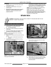
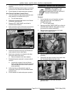
1. Check voltage across heating element wires at limiting and regulating contactor terminals.
A. If voltage is correct, check current draw (step 2).
B. If voltage is not correct, check the following:
1) Voltage supply to steamer.
2) Fuses or breaker blown.
3) Power to contactor coils.
4) Contactors not pulling in. (Mechanical)
2. Check current draw (amps) through heating element lead wires using an amp clamp meter.
A. If current is correct, then heating element is ok.
B. If current is not correct, check element resistance (step 3).
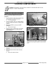
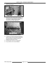
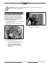
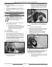
3. Remove one lead wire of each heating element from the regulating contactor and check the individual
element resistance using a VOM.
A. If resistance readings are not correct, replace heating element.
MODEL VOLTAGE TOTAL kW
CURRENT PER
ELEMENT
RESISTANCE PER ELEMENT
(OHMS)
3 Pan
208
1
8.5 10.2 20.4
240
2
8.5 11.8 20.4
480Y/277
3
8.5 10.2 27.1
5 Pan
208 15 18.0 11.5
240 15 20.8 11.5
480Y/277
3
15 18.1 15.3
1
Four elements used.
2
Three elements used.
3
Elements of 480V machines are connected in Wye configuration for 277V across each element.
NOTE: Values in table are nominal. Tolerance is ±10 %.
4. Check steamer for proper operation.
OVERHEAD VIEW OF HEATING ELEMENT