


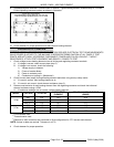
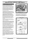
MODEL C24EA - WATER LEVEL CONTROL COMPONENTS
F25213 (May 2006)Page 25 of 52
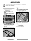
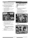
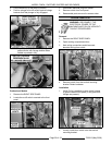
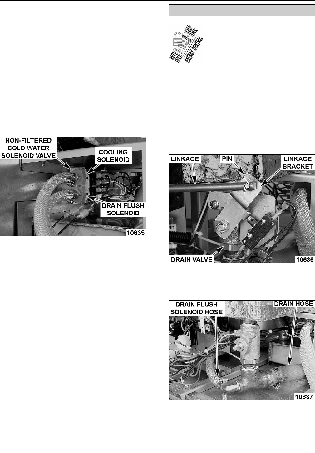
VIEW FROM LEFT SIDE OF STEAMER
6. Reassemble parts removed in reverse order of
removal.
7. Verify that the filtered water supply is connected
to the input of the filtered water solenoid valve.
8. Check steamer for leaks and proper operation.
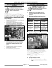
Non-Filtered Cold Water Solenoid Valve
1. Turn off machine to drain steam generator tank.
Allow steamer to complete drain cycle.
A. Turn off water supply.
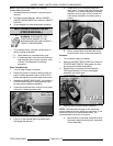
2. Disconnect incoming water hose to non-filtered
cold water solenoid valve.
3. Remove LEFT SIDE PANEL as outlined in
COVERS AND PANELS.
4. Note connection points of electrical connections
then disconnect wiring from solenoid valve.
5. Remove the screws securing non-filtered cold
water solenoid valve to back plate.
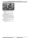
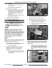
6. Note hose connections to solenoid valve then
disconnect hoses from valve.
A. Remove solenoid valve from steamer.
7. Reassemble parts removed in reverse order of
removal.
A. Connect the outputs of the non-filtered
water cooling solenoid to the drain box and
Tee mounted to the drain valve under the
steam generator.
8. Verify that the non-filtered water supply is
connected to the input of the non-filtered water
solenoid valve.
9. Check steamer for leaks and proper operation.
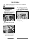
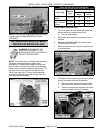
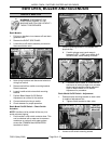
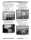
MANUAL DRAIN VALVE (BASIC)
WARNING: DISCONNECT THE
ELECTRICAL POWER TO THE
MACHINE AND FOLLOW LOCKOUT /
TAGOUT PROCEDURES.
Removal
1. Pull out handle to turn off machine and drain
steam generator tank. Allow steamer to
complete drain cycle.
A. Turn off water supply.
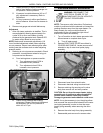
2. Remove the RIGHT SIDE PANEL as outlined in
COVERS AND PANELS. Rear panel can also
be removed for added accessibility.
3. Remove the pin and disconnect the handle
linkage from linkage bracket.
4. Remove the on/off switch and bracket as an
assembly.
5. Disconnect the drain and drain flush hoses from
the Tee located below the drain valve.
6. Remove the drain valve from the steam
generator tank.