– 5 –
INSTALLATION CODES AND STANDARDS
In the United States, Vulcan gas ovens must be installed in accordance with: 1) State and local codes;
2) National Fuel Gas Code, ANSI-Z223.1 (latest edition), available from American Gas Association,1515
Wilson Boulevard, Arlington, VA 22209; 3)ANSI/NFPA 96,
Vapor Removal from Cooking Equipment
(latest edition), available from National Fire Protection Association, Batterymarch Park, Quincy, MA
02269; and 4) National Electrical Code, NFPA-70 (latest edition).
In Canada, Vulcan gas ovens must be installed in accordance with: 1) Local codes; 2) CAN/CGA-
B149.1,
Natural Gas Installation Code
(latest edition) or CAN/CGA-B149.2,
Propane Installation Code
(latest edition), available from Canadian Standards Association, 178 Rexdale Boulevard, Etobicoke,
Ontario, Canada M9W 1R3; and 3) Canadian Electrical Code, CSA Standard C22.2 No. 3,
Electrical
Features of Fuel Burning Equipment
(latest edition).
INSTALLING BASIC OVEN
The basic oven must be installed on 4"
(10 cm) or 6" (15 cm) adjustable legs for counter installation or
be mounted on a modular stand. Installations on concrete bases or other supports restricting air
circulation underneath the oven are not advisable and may void the warranty.
When the oven is mounted on casters, it must be installed with the
casters supplied, a connector (not supplied by Vulcan-Hart) complying
with either ANSI Z21.69 (latest edition) or CAN/CGA-6.16 (latest
edition), and a quick-disconnect device complying with either ANSI
Z21.41 (latest edition) or CAN1-6.9 (latest edition). It must also be
installed with a restraint device to prevent strain on the connector.
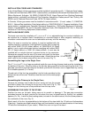
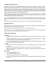
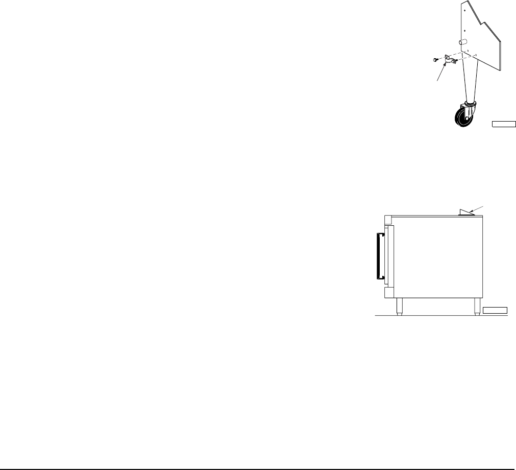
Remove two screws from the rear of the oven and install the tie down
strap shipped with the casters using these screws. Attach the gas line
strain relief to the tie down strap at the rear of the oven (Fig. 1).
Assembling the Legs to the Single Oven
The 4" (
10 cm) or 6" (15 cm) legs are packed inside the oven during shipment and must be installed on
the bottom of the oven. Place the oven on its left side, being careful to avoid scratching the finish. The
gas pipe connection protrudes beyond the back; provide for this when oven is tipped back by resting
it on suitable spacers (2 x 4's etc.).
Thread each of the four leg assemblies into the holes provided on the
bottom corners of the oven. Carefully raise the oven to its normal upright
position.
Assembling the Chimney to the Single Oven
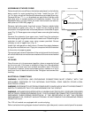
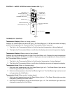
Remove the chimney from inside the oven cavity and use the screws
provided to fasten the chimney to the top rear of the oven (Fig. 2). The
flanges on the chimney are to be positioned over the top cover.
ASSEMBLING THE OVEN TO THE STAND
Position the oven on its back, taking care not to scratch or damage it. The gas pipe connection
protrudes beyond the back; provide for this when the oven is tipped back by resting it on suitable
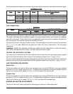
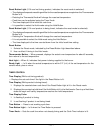
spacers (2 x 4's). Install the two locating studs (included in the stand carton) into the screw plates on
the underside of the oven (Fig. 3).
Attach each of the four leg assemblies to the bottom of the stand with the 12 bolts and lockwashers
(3 per leg). If casters are used instead of legs, put fixed casters in rear and swivel casters in front using
12 bolts and lockwashers (3 per caster). Mount the oven on top of the stand.
Fig. 1
CHIMNEY
PL-52240
Fig. 2
CONNECT
GAS LINE
STRAIN RELIEF
HERE
PL-53563


