


– 6 –
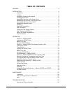
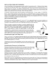
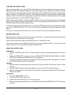
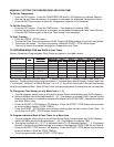
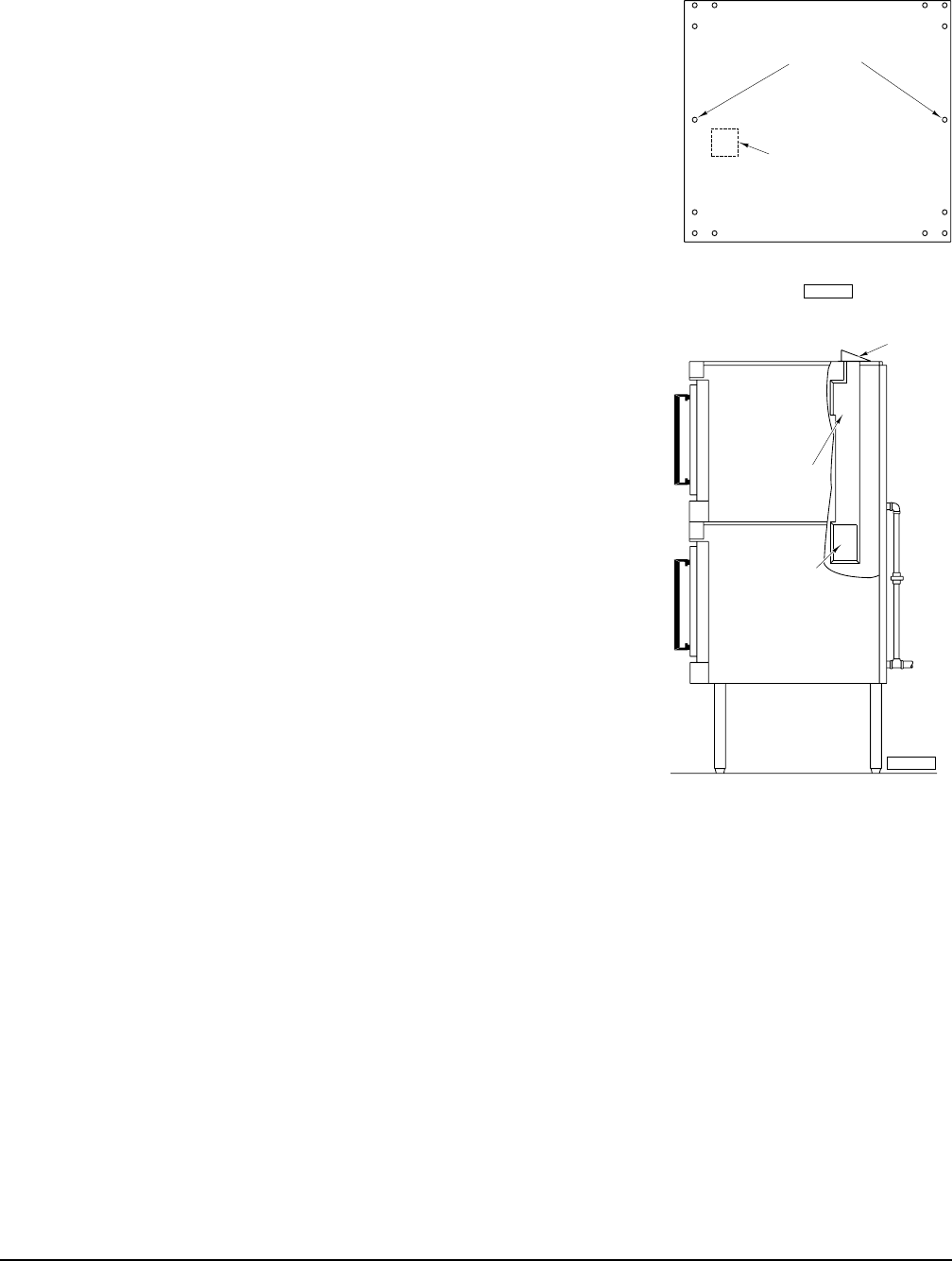
REAR OF TOP OVEN
KNOCK OUT WELDED PLATE
FOR FLUE EXTENSION INSTALLATION
BOTTOM
LOCATING STUDS
PL-52992
FRONT OF TOP OVEN
ASSEMBLING STACKED OVENS
Determine which oven will be on the bottom and place it on its left side,
being careful to avoid scratching the finish. Install the four 16
3
⁄4"
(42.5 cm) legs, using the 24 bolts and lockwashers provided (6 per leg).
Remove the two
7
/16" (1.1 cm) knockouts on each side of the top cover
and place oven in upright position at installation location. Turn the
adjustable feet in or out to level the oven front-to-back and side-to-
side (refer to LEVELING, page 6).
Remove right side panels from both ovens. Remove welded plate
from bottom of upper oven (Fig. 3). Install the two locating studs
(included in the leg stack set) into screw plates on underside of upper
oven (Fig. 3). Place upper oven on top of lower oven using the locating
studs.
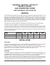
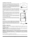
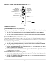
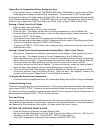
Remove flue extension from upper oven. Install long flue extension
into existing right-angled flue extension in lower oven. Attach long flue
extension to wall of upper oven using screws provided. Secure
chimney to roof of upper oven (Fig. 4).
Install right side panels on both ovens. Connect the piping between
the top oven and bottom oven. Pipe joint compound must be resistant
to the action of propane gases.
The manual gas valve at the bottom of the control panel should remain
off until all electrical connections are made and the ovens are checked
or used.
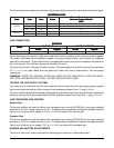
LEVELING
Once the oven is in its permanent position, place a carpenter's level
on the oven rack. If the oven is installed on legs, turn the adjustable
feet in or out to level oven front-to-back and side-to-side. If the oven
is installed on casters, loosen set screws and turn casters in or out to
level oven front-to-back and side-to-side. Retighten set screws after
leveling.
ELECTRICAL CONNECTIONS
WARNING: ELECTRICAL AND GROUNDING CONNECTIONS MUST COMPLY WITH THE
APPLICABLE PORTIONS OF THE NATIONAL ELECTRICAL CODE AND/OR OTHER LOCAL
ELECTRICAL CODES.
WARNING: DISCONNECT ELECTRICAL POWER SUPPLY AND PLACE A TAG AT THE DISCONNECT
SWITCH TO INDICATE THAT YOU ARE WORKING ON THE CIRCUIT.
WARNING: APPLIANCES EQUIPPED WITH A FLEXIBLE ELECTRIC SUPPLY CORD ARE PROVIDED
WITH A THREE-PRONG GROUNDING PLUG. THIS PLUG MUST BE CONNECTED TO A PROPERLY
GROUNDED THREE-PRONG RECEPTACLE. IF THE RECEPTACLE IS NOT THE PROPER
GROUNDING TYPE, CONTACT AN ELECTRICIAN. DO NOT REMOVE THE GROUNDING PRONG
FROM THE PLUG.
The 120 volt models are equipped with a cord and plug.
Refer to electrical wiring diagram located inside the right side panel; remove control panel for access.
Fig. 3
Fig. 4
RIGHT ANGLED
FLUE EXTENSION
LONG FLUE
EXTENSION
CHIMNEY
PL-52221