


VHX SERIES STEAMER - ELECTRICAL OPERATION
F25154 (February 2004)Page 33 of 48
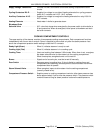
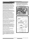
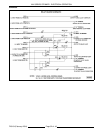
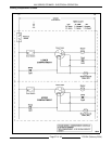
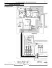
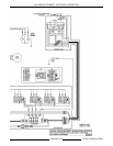
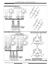
SEQUENCE OF OPERATION
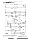
Refer to schematic diagram AI1385 for the electrical
sequence of operation.
Initial Fill and Preheat
1. Conditions.
A. Boiler connected to correct supply voltage
and is properly grounded.
1) Supply voltage transformer energized
and 120VAC is output from
transformer secondary.
2) 120VAC to compartment controls and
one side of the power switch.
B. Power switch off.
C. Cycling pressure switch closed.
D. High limit pressure switch closed.
E. Cold water condenser (CWC) thermostat
open.
F. Automatic blowdown/drain valve (A.B.D.)
open and boiler empty.
G. Water supply valve(s) on.
2. Turn power switch on.
A. Automatic blowdown/drain valve (N.O.) is
energized and closes.
B. Water level control (WLC) energized.
1) High level (HL) relay energized, HL-3
N.O. contacts close.
a. Boiler fill solenoid energized,
water begins filling the boiler (fill
time 4-11 min.).
2) LLCO-1 N.O. contacts remain open.
3) HL LED lit.
C. Auxiliary water level control (AUX WLC)
energized.
1) AUX LLCO-1 N.O. contacts remain
open.
D. 120VAC to common relay terminal on
K1(1) N.O., K3(1) N.O., K3(1) N.C., K3(2)
N.O. , K4(1) N.O., K4(1) N.C contacts.
E. Low Water light lit thru K3(1) N.C.
F. High Pressure light lit thru K4(1) N.C.
G. K2 energized through the high limit
pressure switch (N.C.).
1) K2 contacts K2(1) N.O. & K2(2) N.O.
close, no power transferred.
H. 120VAC to common terminal on AUX
LLCO-1 contacts.
I. 120VAC to common terminal on WLC
LLCO-1 contacts thru cycling pressure
switch (N.C.).
3. Water level reaches LLCO probe for the main
water level control and AUX LLCO probe for the
auxiliary water level control.
A. LLCO relay on water level control
energizes, LLCO-1 contacts (N.O.) close
1) LED on board lights.
2) Cycling contactors B & D energized.
Heating elements remain de-
energized until manual reset switch
pressed.
B. AUX LLCO relay on AUX water level
control energizes, AUX LLCO-1 contacts
(N.O.) close.
1) LED on board lights.
2) K1 is energized thru AUX LLCO-1
N.O. contacts.
a. K1(1) N.O. and K1(2) N.O. close.
b. Ready light on manual reset
switch lit thru K1(1) N.O.
contacts.
NOTE: The LLCO and AUX LLCO relays will
remain energized and LLCO LED’S will remain
lit until the water level drops below the LLCO
probes or the power switch is turned off.
NOTE: The manual reset switch could be
pressed to energize the heating elements but
it’s preferred to let the boiler fill the to the high
level before continuing.
4. Water reaches LL (low level) probe.
5. Water reaches HL (high level) probe.
A. Boiler fill solenoid is de-energized.
B. HL LED goes out.
6. Manual reset switch pressed.
A. K3 is energized.
NOTE: Relay K3 remains energized through
K3(1) N.O. latching circuit.
1) K3(1) N.O. contacts close and K3(1)
N.C. contacts open.
2) Low water light goes out.
3) K3(2) N.O. contacts close.
a. 120VAC to common side of
K4(2) N.O. contacts.
B. K4 is energized.
NOTE: Relay K4 remains energized through
K4(1) N.O. latching circuit.