


VHX SERIES STEAMERS - REMOVAL AND REPLACEMENT OF PARTS
F25154 (February 2004) Page 12 of 48
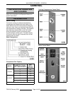
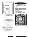
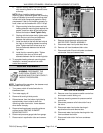
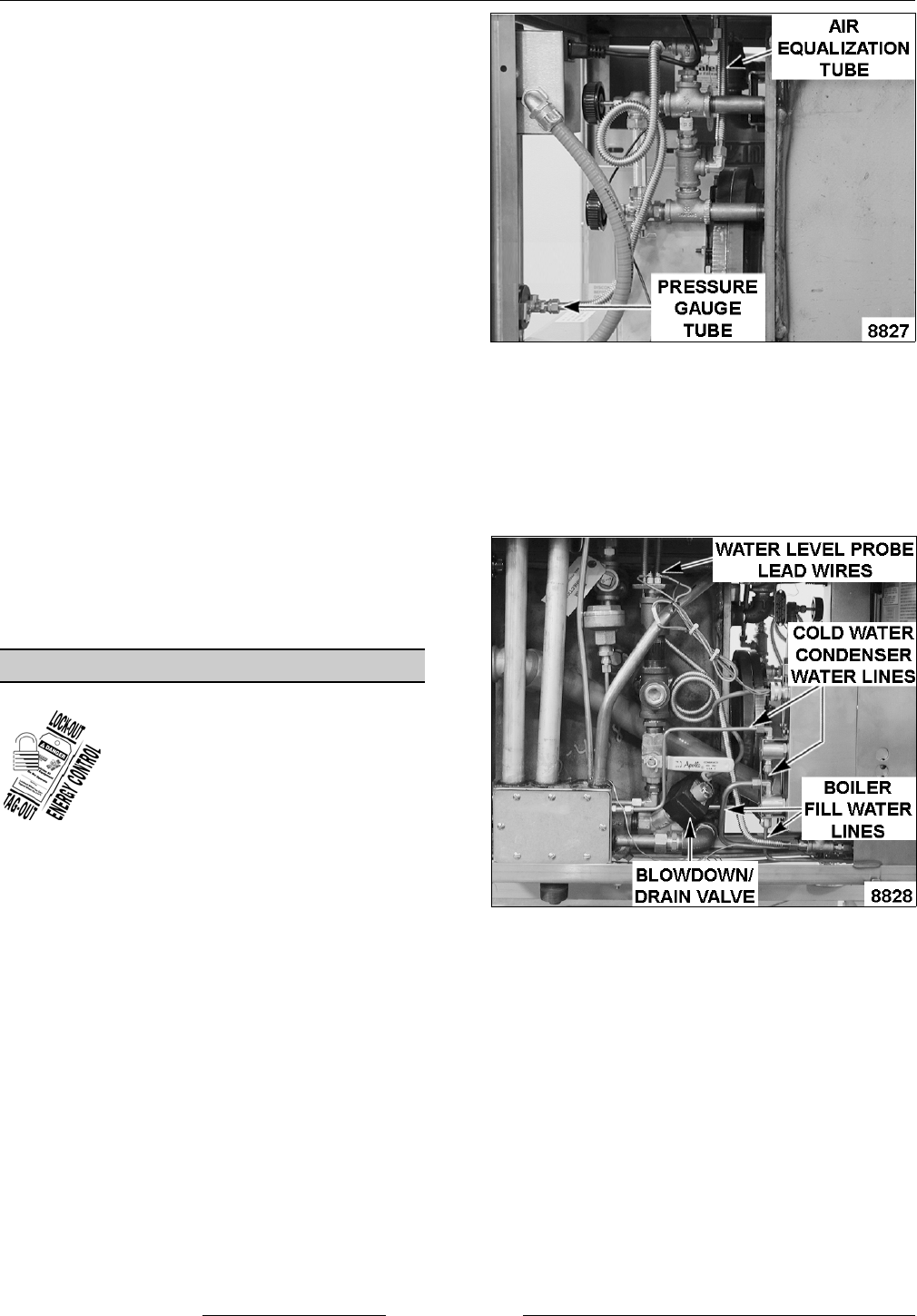
RIGHT SIDE VIEW SHOWN
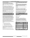
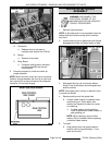
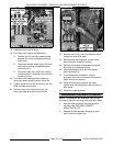
LEFT SIDE VIEW SHOWN
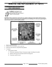
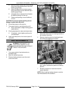
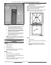
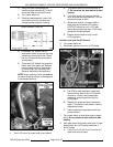
C. Position heating element mounting plate
with mounting studs for the element cover
at the top.
NOTE: When installing heating element
mounting plate
, install and tighten the mounting
bolts as indicated to ensure the mounting plate
is flush with boiler flange and gasket is evenly
compressed. If bolt is not threading properly by
hand, clean out the threads with a 3/8 x 16 tap.
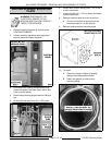
D. Align mounting holes then press and hold
heating element mounting plate against the
gasket. Install two bolts at the top and two
bolts at the bottom. Hand Tighten Only.
E. Starting with the bottom bolts, tighten each
bolt a few turns at a time and alternate
between the bottom and top bolts.
F. Install two bolts at the left and two bolts at
the right on the heating element mounting
plate. Tighten each bolt a few turns at a
time and alternate between the left and
right bolts.
G. Install the four remaining bolts. Tighten
each bolt a few turns at a time and
alternate between the four remaining bolts.
11. To complete heating element mounting plate
installation, reverse procedure from main
control box removal.
BOILER ASSEMBLY
WARNING: DISCONNECT THE
ELECTRICAL POWER TO THE
MACHINE AND FOLLOW LOCKOUT /
TAGOUT PROCEDURES.
NOTE: To perform this procedure, the steamer must
be accessible from all sides.
1. Turn power switch off and allow boiler to
blowdown/drain.
2. Turn water supply off.
3. Remove left and right side panels.
4. Raise steamer from the bottom right side by
approximately three inches to drain the
remaining water from boiler. Lower steamer
when boiler is empty.
5. Remove heating element mounting plate as
outlined under HEATING ELEMENT
MOUNTING PLATE.
6. Disconnect pressure gauge tube from gauge.
7. Disconnect air equalization tube and remove.
8. Remove gauge glass as outlined under
WATER LEVEL GAUGE ASSEMBLY.
9. Disconnect water level probe lead wires.
10. Remove coil from blowdown/drain valve.
11. Disconnect boiler fill and cold water condenser
valve water lines and remove lines.
12. Remove cover from pressure switch control box
and loosen conduit locking nut.
13. Remove mounting screws for pressure switch
control box.
14. Disconnect pressure relief valve drain line at
the valve.
15. Disconnect water level probe housing air
equalization tube and remove tube.
16. Disconnect water level probe housing drain line
from condenser drain box.
17. Disconnect boiler drain line from condenser
drain box.