


VHX SERIES STEAMER - SERVICE PROCEDURES AND ADJUSTMENTS
F25154 (February 2004) Page 22 of 48
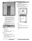
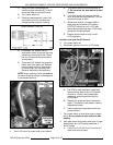
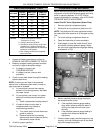
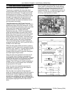
HEATING ELEMENT TEST
VOLTAGE
KW PER
ELEMENT
AMPS PER
ELEMENT
OHMS PER
ELEMENT
208 9.0 14.4 14.4
240 9.0 12.5 19.2
480 9.0 6.3 76.8
208 10.5 16.9 12.4
208 12.0 19.3 10.8
240 12.0 16.7 14.4
480 12.0 8.3 57.6
NOTES:
1. Values in the table are nominal.
Tolerance is +5/-10%.
2. Voltage values are @ 60HZ.
3. Resistance values (ohms) are @ room
temperature. If heating elements are
above room temperature, the measured
resistance will be greater.
4. Each heating element has 3 separate
internal elements.
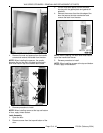
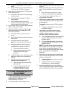
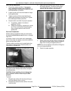
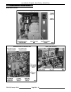
1. Access the heating elements as outlined in
REMOVAL AND REPLACEMENT OF PARTS.
2. Measure voltage at heating element terminals
and verify it against data plate voltage.
A. If voltage is incorrect, see
TROUBLESHOOTING.
B. If voltage is correct, continue with
procedure.
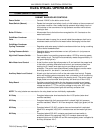
3. Check current draw (amps) through the heating
element lead wires.
NOTE: Checking current draw is the preferred
method over a resistance check when a clamp on
type amp meter is available.
A. If current draw is correct then heating
element is functioning properly. See table
for proper values.
B. If current draw is not correct, turn power
switch off and disconnect the electrical
supply.
1) Install a replacement heating element.
C. If unable to check current draw, a
resistance check may indicate a
malfunctioning element.
1) Turn power switch off and disconnect
power to machine.
2) Remove lead wires from heating
element and check resistance (ohms).
See table for proper values.
4. Check for proper operation.
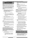
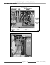
COOKING COMPARTMENT
NOTE: Before proceeding with intake shut-off valve
adjustment, monitor boiler pressure gauge and verify
boiler is operating between 10-12 PSI. If boiler
pressure adjustment is necessary, refer to CYCLING
PRESSURE SWITCH ADJUSTMENT.
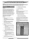
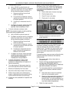
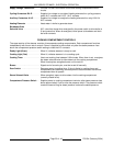
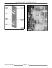
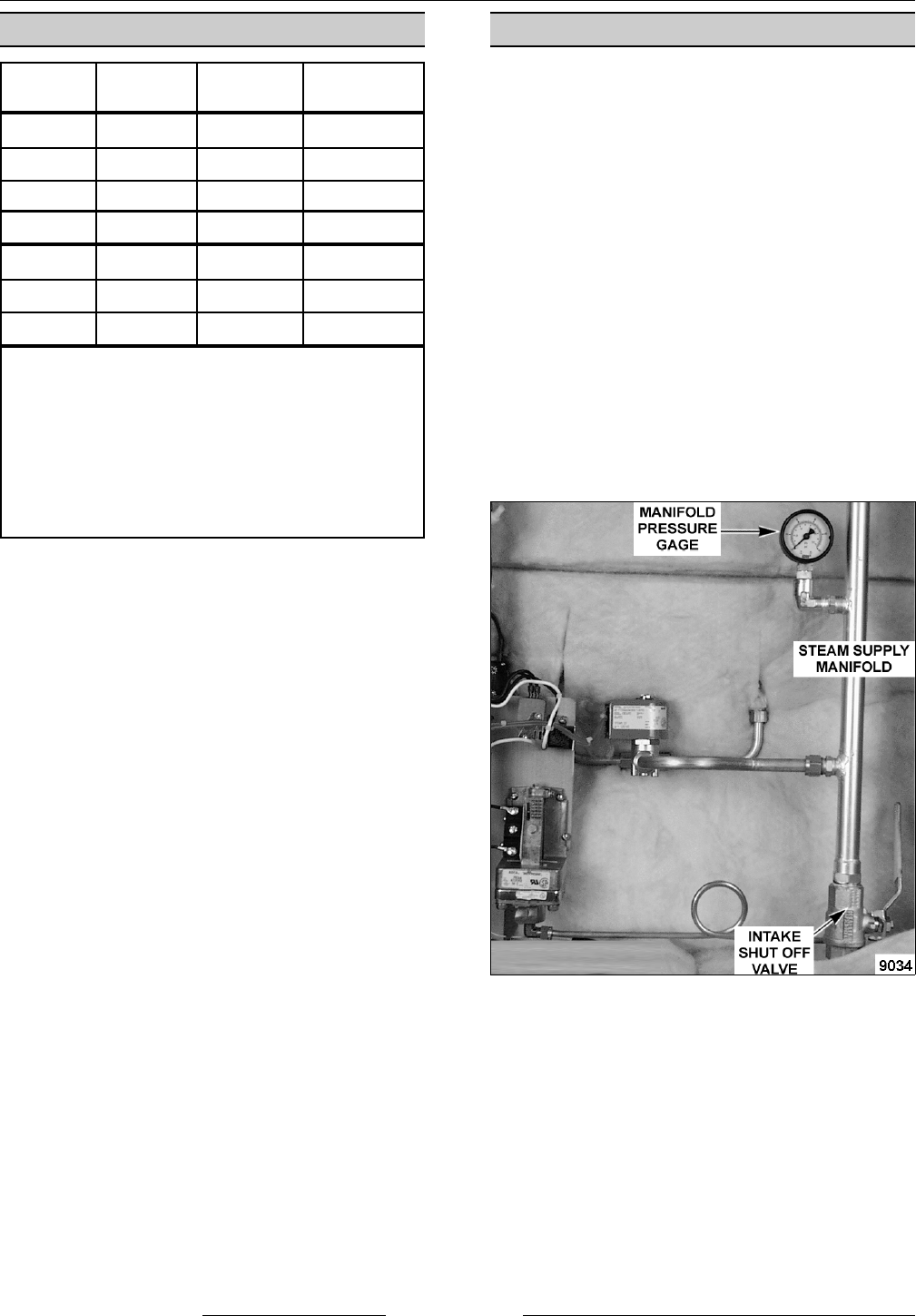
Intake Shut-Off Valve Adjustment (Steam Flow)
1. Remove right side compartment panel.
2. Allow boiler to fully pressurize (heat turns off).
NOTE: The intake shut-off valve adjustment should
be made while boiler pressure is at the upper cycling
limit.
3. Turn both cooking compartment timers on.
4. Open the intake shut-off valve completely.
5. Slowly begin to close the intake shut-off valve
and monitor manifold pressure gauge. Adjust
the valve until manifold pressure gauge reading
is between 8-10 PSI.
6. Monitor manifold pressure gauge reading for
two complete boiler cycles.
A. If the manifold pressure gauge reading
stays within tolerance while the boiler is
cycling, the intake shut-off valve is set
correctly.
B. If the manifold pressure gauge reading is
outside of the tolerance repeat the
adjustment.
7. Once the steam supply manifold pressure is set
correctly, turn both cooking timers off and install
right side compartment panel.