


VHX SERIES STEAMER - SERVICE PROCEDURES AND ADJUSTMENTS
F25154 (February 2004)Page 19 of 48
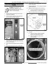
B. Verify Low Water light is lit (front control
panel).
C. Verify 120VAC is on Aux LLCO COM, and
0 volt is on Aux LLCO N.O. contacts.
9. When water level reaches Aux LLCO probe as
boiler continues to fill:
A. Verify Aux LLCO LED is lit on the auxiliary
low water board.
B. Verify the green ready light is lit (front
control panel).
C. Verify 120VAC is on the Aux LLCO
common and normally open contacts of the
auxiliary water level control board.
10. Open the ball valve on probe housing assembly.
This will allow boiler to drain.
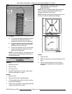
11. When water level is no longer visible in sight
glass and is below LLCO probe; Aux LLCO
circuit should activate.
A. Low water light turns on (front control
panel).
B. Aux LLCO led turns off on the auxiliary low
water board.
C. Press reset switch to verify lockout
condition. Low water light should remain
on.
D. If lockout condition does not occur,
immediately turn power switch off.
1) Disconnect power to machine.
2) Replace auxiliary low level cut-off
control and check for proper
operation.
E. If lockout condition is ok, verify the auxiliary
water level control circuit is functioning
properly.
F. Close the ball valve on probe housing
assembly and allow boiler to fill.
1) Verify low water light turns off (front
control panel).
2) Press the reset switch and verify
auxiliary contactors A & C are
energized and boiler is heating.
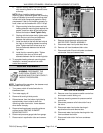
CYCLING PRESSURE SWITCH
ADJUSTMENT
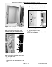
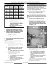
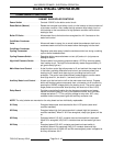
1. Access cycling pressure switch as outlined
under PRESSURE SWITCH CONTROL BOX
COMPONENTS in REMOVAL AND
REPLACEMENT OF PARTS.
2. Turn power switch on (boiler begins to fill).
3. Press reset switch and verify high pressure light
turns off.
4. When green ready light comes on, press reset
switch to begin heating (low water light turns
off).
A. Allow boiler to fully pressurize. Cycling
pressure switch opens and heating stops.
5. Turn one cooking compartment timer on to
exhaust steam from boiler.
6. Monitor boiler pressure gauge for two complete
cycles. Note pressure at which the heat comes
on and goes off.
The heat should come on at 10 PSI and go off
at 12 PSI.
A. If pressure readings differ, continue with
procedure to adjust.
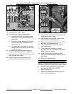
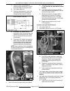
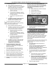
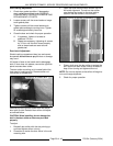
7. Two pressure adjustment screws extend
through the top of switch cover. A clockwise
rotation increases pressure; a counter-
clockwise rotation decreases pressure.
A. Turn the adjustment screw above right side
pointer to obtain the proper cut-out (off)
pressure setting.
B. Turn the adjustment screw above the left
side pointer to obtain the proper cut-in (on)
pressure setting.
NOTE: The screw directly above the right side
pointer adjusts cut-out (off) and cut-in (on) set
points without changing the differential. The
screw directly above the left side pointer adjusts
cut-in (on) set point and changes the
differential.
8. Monitor boiler pressure gauge for two complete
cycles and note the pressure at which the heat
comes on and goes off.
A. If pressures are correct, pressure switch is
properly adjusted.
B. If pressures are not correct, repeat the
adjustment for up to three attempts.
9. If the above adjustment cannot be obtained,
install a replacement pressure switch and adjust
pressure settings as outlined in this procedure.