


FULL SIZE ELECTRIC CONVECTION OVEN - REMOVAL AND REPLACEMENT OF PARTS
F25105 (December 2001) Page 10 of 60
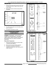
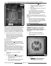
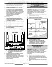
LEFT SIDE ELEMENTS SHOWN
NOTE:
The mounting bracket is sealed with RTV
which may still hold the element after the screws are
removed. Also, in some cases, the ring terminal
connected to the element may interfere with easy
removal. If access to the left side panel and/or the
top panel is available, see "ALTERNATE ACCESS".
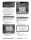
6. Disconnect the lead wires from the element.
7. Clean RTV residue from the mating surface
inside the oven, apply new high temperature
RTV to the heating element mounting bracket
and reverse procedure to install.
8. Check for proper operation.
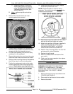
Alternate Access
If the heating element is not
removing easily from
inside the oven cavity, and access to the left side
panel and/or the top panel is available, this alternate
removal method may be used.
NOTE:
On stacked ovens, if the bottom oven is
being serviced and the heating element to replace is
on the right side, the ovens must be unstacked to
access the heating element terminals through the
top. Once unstacked, follow the removal procedure
below.
1. Perform steps 1 thru 4 under "FRONT
ACCESS".
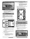
2. If the element is on the left
side:
A. Remove the left side panel and pull back
the insulation at the top to expose the
element terminals.
B. Remove the lead wires from the element
being replaced. Proceed to step 4.
3. If the element is on the right
side:
A. Remove the top panel and pull back the
insulation to expose the element
terminals.
B. Remove the lead wires from the element
being replaced.
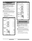
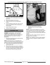
4. From the same element, remove the two
clamps holding the element vertical, the
screw’s securing mounting bracket at the top,
and then remove the element.
NOTE:
The mounting bracket is sealed with RTV
which may still hold the element after the screws are
removed.
5. Clean RTV residue from the mating surface
inside the oven, apply new high temperature
RTV to the heating element mounting bracket
and reverse procedure to install.
6. Check for proper operation.
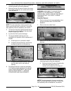
BLOWER AND MOTOR
WARNING:
DISCONNECT THE ELECTRICAL
POWER TO THE MACHINE AT THE MAIN
CIRCUIT BOX. PLACE A TAG ON THE CIRCUIT
BOX INDICATING THE CIRCUIT IS BEING
SERVICED.
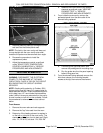
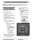
1. Take out the racks and rack supports.
2. Remove screws securing baffle panel and
remove the panel.
3. If replacing:
A. Blower Only
- Loosen set screws on
blower hub and using a bearing puller,
remove blower from motor shaft.