


FULL SIZE ELECTRIC CONVECTION OVEN - REMOVAL AND REPLACEMENT OF PARTS
F25105 (December 2001) Page 14 of 60
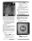
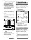
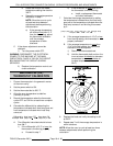
5. Lift up on the door assembly and swing the
right side out then move the assembly to the
left to clear the slots in the upper door sill.
6. Lay the door assembly on a flat cushioned
surface for disassembly.
7. Reverse procedure to install door assembly
and check for proper adjustment as outlined
under "DOOR ADJUSTMENT", "DOOR CHAIN
ADJUSTMENT (SIMULTANEOUS DOORS)"
and "DOOR SWITCH ADJUSTMENT" in
"SERVICE PROCEDURES AND
ADJUSTMENTS".
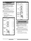
Disassembly
1. Remove the door assembly as outlined in
"OVEN DOORS (SIMULTANEOUS)" under
"ASSEMBLY REMOVAL".
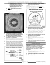
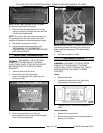
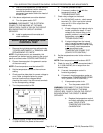
2. Remove the door chain by loosening one of the
turnbuckles.
3. Loosen the set screw on the sprocket of door
being replaced.
4. Drive out the spirol pin from the sprocket of
door being replaced.
5. Remove the door from lower sill bearings and
sprocket.
A. Door assembly parts are now accessible
for inspection and/or replacement if
necessary.
6. Reverse procedure to re-assemble the door
assembly parts and check for proper
adjustment as outlined under "DOOR CHAIN
ADJUSTMENT (SIMULTANEOUS DOORS)" in
"SERVICE PROCEDURES AND
ADJUSTMENTS".
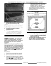
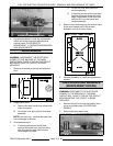
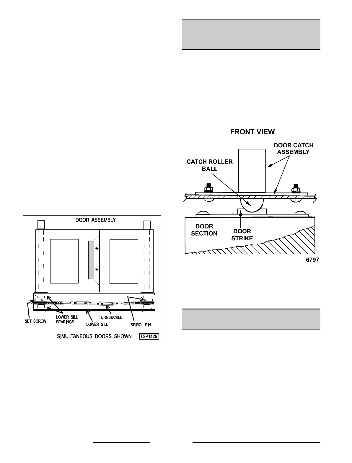
DOOR CATCH ROLLER
ASSEMBLY
(INDEPENDENT DOORS)
WARNING:
DISCONNECT THE ELECTRICAL
POWER TO THE MACHINE AT THE MAIN
CIRCUIT BOX. PLACE A TAG ON THE CIRCUIT
BOX INDICATING THE CIRCUIT IS BEING
SERVICED.
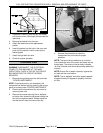
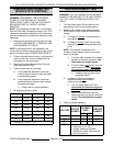
1. Remove the top front cover as outlined under
“COVERS AND PANELS”.
2. Remove the catch roller assembly.
3. Reverse procedure to install.
4. Adjust the catch roller as outlined under
“DOOR CATCH (ROLLER) ADJUSTMENT
(INDEPENDENT DOORS)” in “SERVICE
PROCEDURES AND ADJUSTMENTS”.
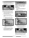
MECHANICAL (KX)
THERMOSTAT
WARNING:
DISCONNECT THE ELECTRICAL
POWER TO THE MACHINE AT THE MAIN
CIRCUIT BOX. PLACE A TAG ON THE CIRCUIT
BOX INDICATING THE CIRCUIT IS BEING
SERVICED.
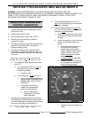
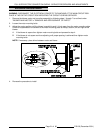
1. Remove the racks and right rack support.
2. Remove the thermostat knob and mounting
screws from the control panel and then remove
the control panel.
3. Remove the probe guard from the oven cavity
wall.