


FULL SIZE ELECTRIC CONVECTION OVENS - SERVICE PROCEDURES AND ADJUSTMENTS
F25105 (December 2001)Page 25 of 60
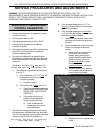
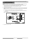
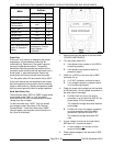
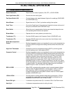
MENU
ALTERNATING ON
DISPLAY
PARAMETER DATA
Celsius_Fahrenheit C_F F
Guard Band gb 4000
Temperature
Compensation
tcnP OFF
Input Type 1 InP1 J
Range Low 1 rL1 75
Range High 1 rH1 500
Hysteresis HYS1 3
Calibration Offset CAL1 0
Exit Setup Mode and
return to Operation
Mode.
set point temperature is
displayed or if call for
heat, dashes (----)
displayed.
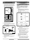
Probe Test
If the oven is not heating or displaying the proper
temperature, the temperature probe may be
malfunctioning. Determine if the probe is good or
causing the operational problem. Temporarily,
disconnect the existing probe lead wires from the
computer control and connect the lead wires from a
known good "J" type thermocouple. Secure the
sensing end of the thermocouple near the probe.
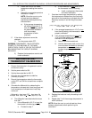
Turn the power switch ON and set the dial to 350°F.
If the oven reaches the set temperature and cycles
with the temporary thermocouple, then the existing
probe is malfunctioning. Replace temperature probe
with the correct part and check for proper operation.
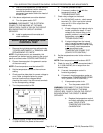
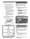
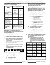
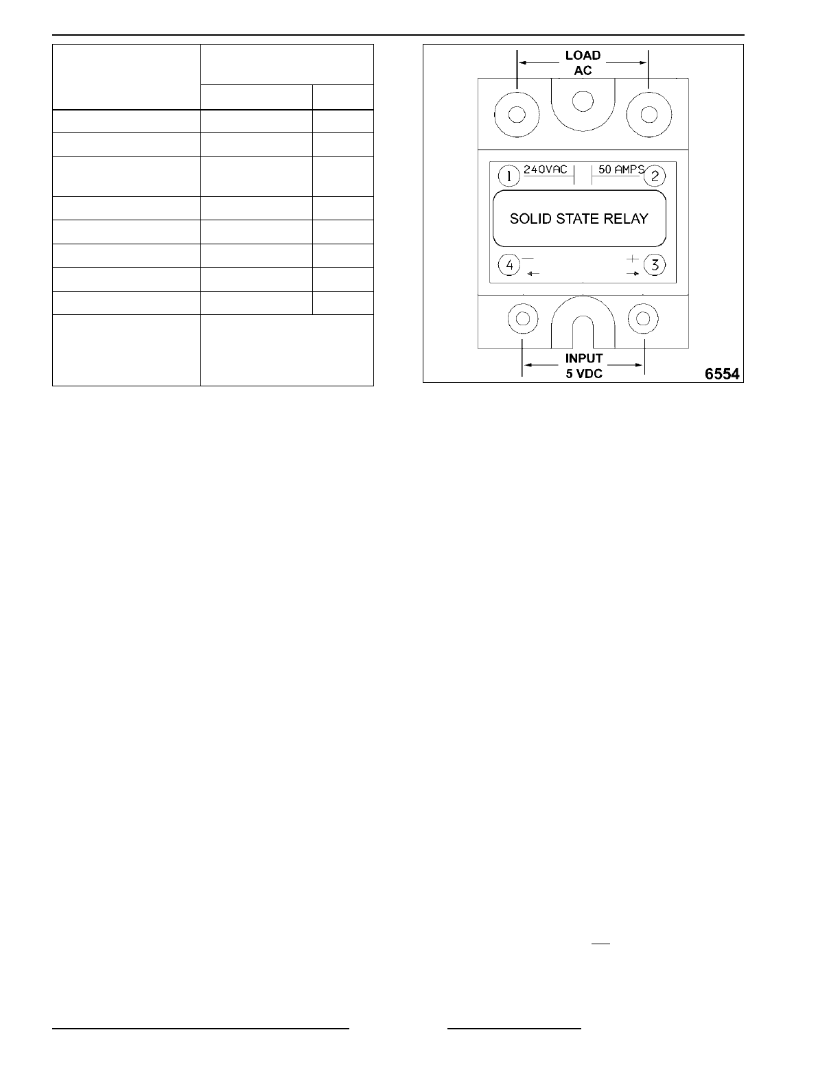
Solid State Relay Test
The solid state relays "SSR1 or SSR2" supply power
to the blower motor "high" or "low" fan speed
terminals when the SSR is energized by the output
voltage from the computer.
To test solid state relay "SSR1" (high fan speed),
the computer control should be in the "Normal
Cooking Mode". To test solid state relay "SSR2"
(low fan speed), the computer control should be in
the "Cook & Hold Mode".
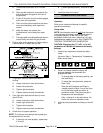
1. Remove the right side panel as outlined under
"COVERS AND PANELS".
2. Turn the power switch ON.
A. If the blower motor comes on, the SSR is
functioning properly.
B. If the blower motor does not come on,
proceed to step 3.
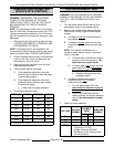
3. Check for +5 VDC on the input side of SSR
(terminals 3 & 4).
A. If +5 VDC is present, continue to step 4.
B. If no voltage is present, computer control
is not functioning properly.
4. Check for proper input voltage on the load side
of SSR terminal 1 and the power connection on
the other side of the supply.
A. On 208 & 240 volt ovens, the supply
connection is on the terminal block (L2 for
single phase, L3 for three phase).
The measured voltage should be identical
to the supply.
B. On 480 volt ovens, the supply connection
is on the secondary side of the 480V
transformer, terminal X4 (wire # 79).
The measured voltage should be 240
volts.
5. If input voltage is correct on the load side of
SSR terminal 1, proceed to step 6.
A. If input voltage is not
correct, find the
source of the problem.
6. Check output voltage on the load side of SSR
terminal 2.