


VHX SERIES STEAMER - SERVICE PROCEDURES AND ADJUSTMENTS
F25154 (February 2004) Page 20 of 48
HIGH LIMIT PRESSURE
SWITCH ADJUSTMENT
NOTE: Before the high limit pressure switch can be
adjusted, the cycling pressure switch must be
temporarily removed from the boiler control circuit.
This allows the boiler to pressurize above the normal
operating range. After the high limit pressure switch
is properly adjusted, the cycling pressure switch
must be returned to its normal operating
condition. Follow the procedure as outlined in the
steps below.
1. Access cycling pressure switch as outlined
under PRESSURE SWITCH CONTROL BOX
COMPONENTS in REMOVAL AND
REPLACEMENT OF PARTS.
A. Remove cover from cycling pressure
switch.
B. Connect a jumper wire between the two
electrical terminals to
temporarily
remove
the cycling pressure switch from the boiler
control circuit.
2. Reconnect power to machine and turn power
switch on (boiler begins to fill).
3. Press reset switch and verify high pressure light
turns off.
4. When green ready light comes on, press reset
switch to begin heating (low water light turns
off).
NOTE: A
pressure relief valve with a 15 PSI setting,
serves as back-up to the high limit pressure switch.
5. Monitor boiler pressure gauge. Note pressure at
which the high limit pressure switch opens (high
pressure light turns on).
The switch should open at boiler pressures no
less than 14.5 PSI but no greater than 15.0 PSI
(MAX).
A. If pressure reading differs, continue with
procedure to adjust.
CAUTION: While making the adjustment, do not
press on the wheel with extreme force. The
switch may rotate and develop a leak at the
compression fittings or in some cases, the rear
lead wire may touch the control box and create
an electrical short.
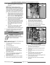
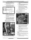
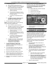
6. Turn adjustment wheel to change high limit
pressure switch setting.
A. A counterclockwise rotation lowers the
pressure switch set point; a clockwise
rotation raises the pressure switch set
point.
NOTE: For every click of the adjustment wheel,
the pressure setting is changed approximately
1/8 PSI.
NOTE: Make the adjustment in small
increments.
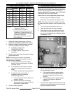
7. After adjusting high limit pressure switch, the
boiler pressure must be reduced to check the
pressure setting.
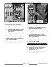
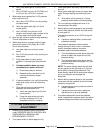
A. Remove left side boiler base panel to
access the manual ball valve on the probe
housing assembly.
WARNING: THE STEAMER AND ITS PARTS ARE
HOT. USE CARE WHEN OPERATING, CLEANING
OR SERVICING THE STEAMER. THE BOILER
CONTAINS LIVE STEAM. STAY CLEAR WHEN
OPENING THE VALVE.
B. Open the manual ball valve to release
boiler pressure and monitor the boiler
pressure gauge.
NOTE: High limit pressure switch resets at
approximately 12 PSI (not adjustable).
C. When pressure is reduced to
approximately 8 PSI, close the ball valve.
D. Press reset switch to reset the high
pressure safety circuit and begin heating
(high pressure light turns off).
8.
Monitor boiler pressure gauge and note the
pressure at which the high limit pressure switch
opens.
A. If pressure is correct, the high limit
pressure switch is properly adjusted.
B. If pressure is not correct, repeat the
adjustment for up to three attempts.
9. If the above adjustment cannot be obtained,
install a replacement high limit pressure switch
and adjust as outlined in this procedure.
10. After the high limit pressure switch is properly
adjusted, disconnect power to machine and
allow boiler to blowdown/drain.
11. Remove jumper wire from cycling pressure
switch to return the switch to its normal
operating condition.
12. Check for proper operation.
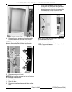
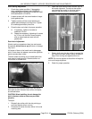
BOILER FILL AND COLD WATER
CONDENSER SOLENOID VALVES
1. Access boiler fill and cold water solenoid valves
as outlined under PRESSURE SWITCH
CONTROL BOX COMPONENTS in REMOVAL
AND REPLACEMENT OF PARTS.
2. Turn power switch on (boiler begins to fill).