


VHX SERIES STEAMERS - REMOVAL AND REPLACEMENT OF PARTS
F25154 (February 2004) Page 8 of 48
4) Disconnect lead wires from other
components as necessary then
remove pressure switch mounting
panel.
5) Remove screws securing switch to
panel.
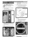
B. High limit pressure switch.
1) Disconnect compression fittings from
switch then remove from box.
C. Boiler fill or cold water condenser valve.
1) Turn water supply off and disconnect
compression fittings from valve.
2) Remove valve bracket mounting
screws.
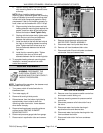
D. Main or auxiliary water level control board
1) Compress locking tab on the board
mounting standoffs and remove
control board.
5. Reverse procedure to install.
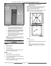
NOTE: Before installing the cycling pressure switch,
use pressure scale on the switch to preset the
approximate cut-out (off) and cut-in (on) set points.
A. Adjust the installed pressure switch
(cycling or high limit) as outlined in
SERVICE PROCEDURES AND
ADJUSTMENTS.
6. Check for proper operation.
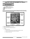
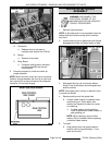
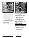
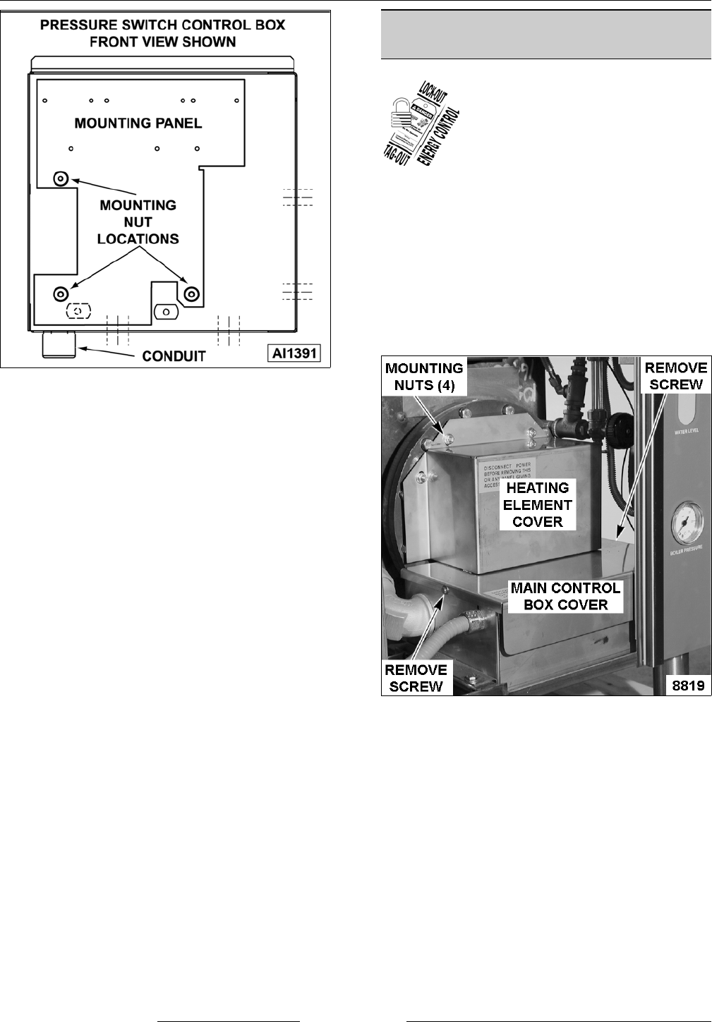
MAIN CONTROL BOX
COMPONENTS
WARNING: DISCONNECT THE
ELECTRICAL POWER TO THE
MACHINE AND FOLLOW LOCKOUT /
TAGOUT PROCEDURES.
CAUTION: Certain components in this system
are subject to damage by electrostatic discharge
during field repairs. A field service grounding kit
is available to prevent damage. The field service
grounding kit must be used anytime a control
board is handled.
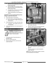
1. Open the cabinet base door.
2. Remove heating element cover then main
control
box cover.
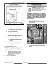
3. Disconnect lead wires from component being
replaced.