


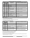
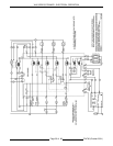

VHX SERIES STEAMER - ELECTRICAL OPERATION
F24700 (October 2001)Page 49 of 68
3. Water level reaches LLCO (low water level cut-
off) probe for the water level control and to the
auxiliary LLCO probe for the auxiliary low level
cut-off control.
A. LLCO relay energizes, LLCO contacts
(N.O.) CLOSE and LED lights.
NOTE:
No power is transferred until ignition
sequence starts.
B. Aux. LLCO relay energizes, LLCO
contacts (N.O.) CLOSE and LED lights.
NOTE:
The LLCO and aux. LLCO relays will remain
energized and LLCO LED’S will remain lit until the
water level drops below the LLCO probes or the
power switch is turned OFF.
4. Water reaches LL (low level) probe.
5. Water reaches HL (high level) probe.
A. Fill solenoid is de-energized.
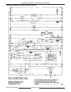
6. Press the manual reset switch.
A. Relay coil (R1) energized.
1) High pressure light turns OFF.
B. Relay coil (R3) energized.
1) Low water light turns OFF.
2) Transformer (T1) energized.
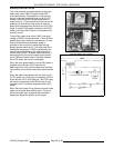
7. 24VAC is connected through the cycling
pressure switch contacts to the following
components:
A. Normally open (N.O.) side of the air
pressure switch.
NOTE:
No power is transferred until air
pressure switch CLOSES.
B. Relay coil (R2) is energized and R2
contacts (N.O.) CLOSE.
1) 120VAC is supplied to the
combustion air blower and blower
starts.
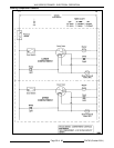
C. Once the combustion blower develops
sufficient pressure, the air pressure switch
CLOSES.
1) 24VAC is then applied to the Ignition
control module and the ignition cycle
starts.
a. Pilot voltage (PV) N.O. contacts
CLOSE.
b. Pilot gas valve energized, pilot
valve opens for gas to flow and
Ignitor begins sparking to light
pilot.
2) Pilot ignition is established (pilot lit)
and a micro amp flame "sense"
current is sent back to the ignition
module through the ignition cable.
3) Main voltage (MV) N.O. contacts
CLOSE.
a. Main gas valve OPENS, burner
lights and boiler begins to heat
up.
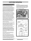
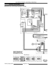
NOTE:
As boiler heats up and builds pressure,
some by-pass water/steam is produced which
runs into the steam drain box. This causes the
cold water condenser (CWC) solenoid to cycle,
cooling the drain water and condensing any
steam vapors before exiting the drain. The
CWC solenoid is powered by the CWC
thermostat.
NOTE:
On initial cold startup only, the boiler
pressure may overshoot and cause the
mechanical pressure relief valve to OPEN
momentarily.
b. As long as the ignition control
module senses a burner flame,
the internal main voltage (MV)
contacts (N.O.) on the ignition
module remain closed, and main
gas valve stays ON.
c. If sparking is allowed to continue
for a total of 90 seconds, then
the ignition module locks out
power to the gas valve (pilot
valve and main valve remain
closed). The module remains
locked out until the power switch
is turned to OFF then ON and
the manual reset switch is
pressed to re-start the ignition
trial cycle.
8. Boiler steam pressure reaches upper limit set
point of 10 PSI (approximately 15 min).
A. Cycling pressure switch opens and power
is removed from the following
components:
1) Combustion air pressure switch
normally open (N.O.) terminal.
2) Relay coil (R2) returning R2 contacts
to there N.O. shelf state.
a. Combustion air blower de-
energized.
B. Ignition control module is de-energized,
PV and MV contacts OPEN.
1) Main gas solenoid valve de-
energizes, gas flow shuts OFF and
burner goes out.
9. Boiler steam pressure drops below lower limit
set point of 8 PSI and the cycling pressure
switch CLOSES.
A. Boiler steam pressure is maintained by the
cycling of the pressure switch between the