


VPX SERIES STEAMER - ELECTRICAL OPERATION
F25111 (March 2002)
Page 14 of 20
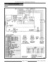
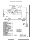
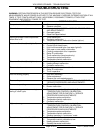
ELECTRICAL OPERATION
COMPONENT FUNCTION
Buzzer ..................
Signals end of a "cook" cycle when cooking time expires.
Contactor ...............
Supplies line voltage to heating element assembly.
Relay R1 ................
Supplies power to temperature control.
Transformer .............
Provides 240V to the control circuit (480V only).
Heater Light (green) ......
Indicates steamer is heating.
Low Water Light (red) .....
Indicates additional water is required in cooking compartment.
Cooking Mode Switch
(with pilot lights) .........
Supplies 240V to the control circuit. Two internal "pilot" lights indicate the
cooking mode selected. Timed mode is amber; Continuous mode is red.
Door Switch .............
Removes control circuit power from steamer when door is opened.
High Limit
Thermostat ..............
Protects steamer by removing control circuit power if the heating element
assembly temperature goes above 350°F (+/-15; 50°F differential).
Temperature Control .....
Monitors temperature probe and cycles power to heater contactor for steam
generation.
Standby Thermostat ......
Maintains steamer at a standby temperature of 168°F (+5/-8) when "cook" timer
is off (timed mode only).
Timer ...................
Counts "cook" time of product when time is dialed and energizes buzzer when
time expires. To silence buzzer, dial must be turned to off.
Temperature Probe .......
Senses cooking compartment temperature and sends a corresponding DC
voltage back to the temperature control (J-type thermocouple).
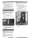
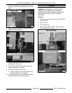
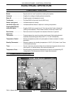
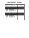
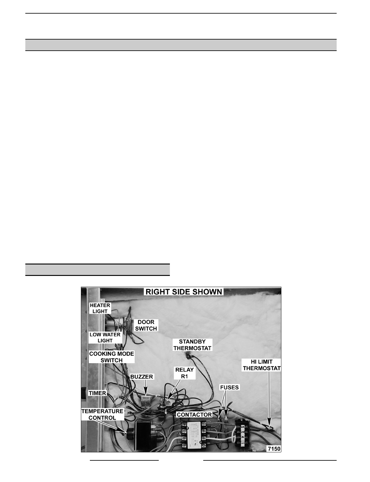
COMPONENT LOCATION