VPX SERIES STEAMERS - REMOVAL AND REPLACEMENT OF PARTS
F25111 (March 2002)
Page 5 of 20
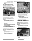
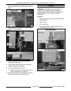
4. Reverse procedure to install replacement
component and check steamer for proper
operation.
NOTE:
If replacing temperature control, see
"TEMPERATURE CONTROL CALIBRATION -
ADJUSTMENT FOR ELEVATION" in "SERVICE
PROCEDURES AND ADJUSTMENTS".
TIMER
WARNING:
DISCONNECT THE ELECTRICAL
POWER TO THE MACHINE AT THE MAIN
CIRCUIT BOX. PLACE A TAG ON THE CIRCUIT
BOX INDICATING THE CIRCUIT IS BEING
SERVICED.
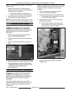
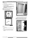
1. Remove right side panel as outlined under
"COVERS AND PANELS".
2. Disconnect lead wires to timer.
3. Loosen two set screws on dial and pull timer
knob from shaft.
4. Remove nut from timer shaft and remove timer.
5. Reverse procedure to install.
STANDBY THERMOSTAT
WARNING:
DISCONNECT THE ELECTRICAL
POWER TO THE MACHINE AT THE MAIN
CIRCUIT BOX. PLACE A TAG ON THE CIRCUIT
BOX INDICATING THE CIRCUIT IS BEING
SERVICED.
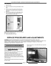
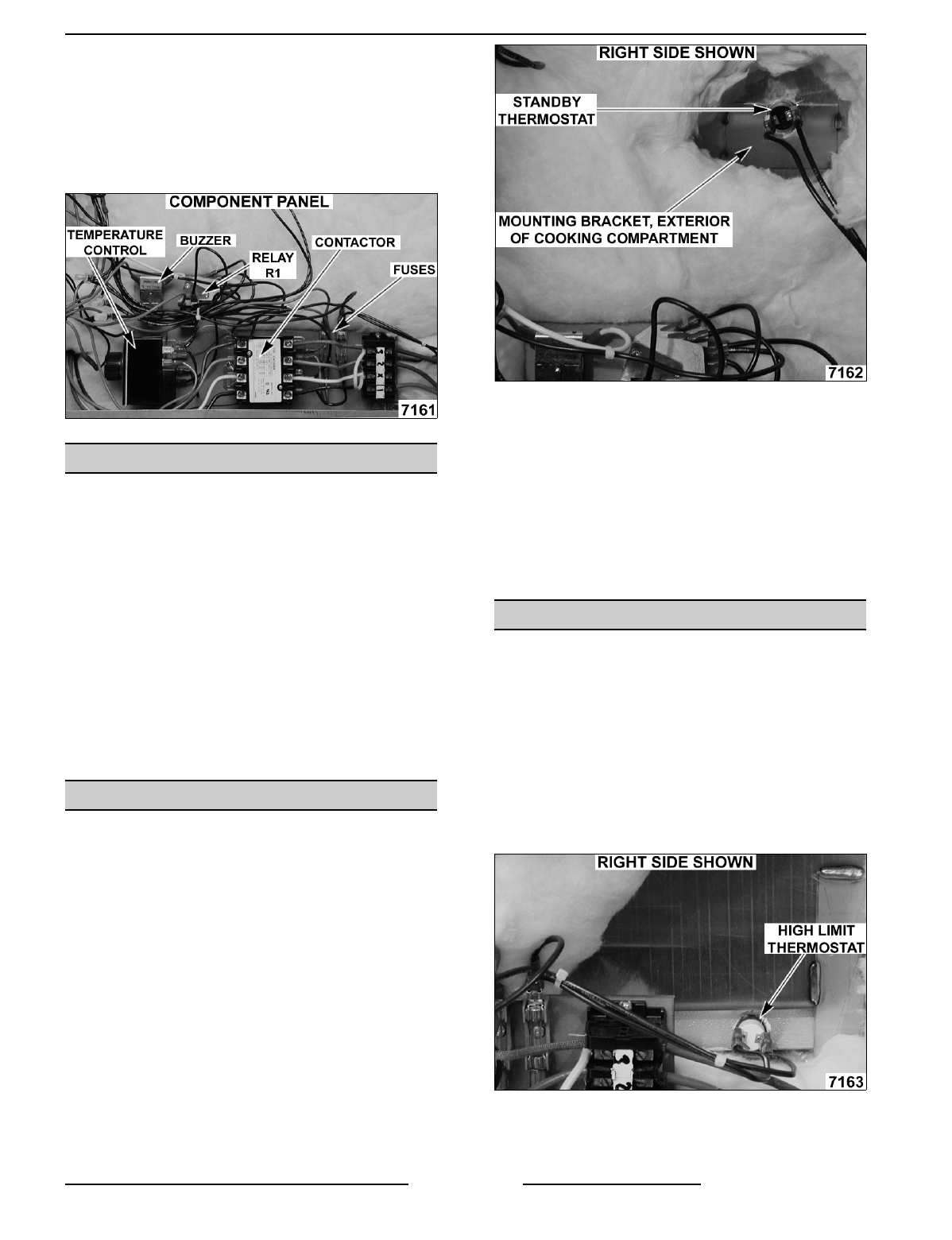
1. Remove right side panel as outlined under
"COVERS AND PANELS".
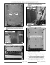
2. Pull insulation back to expose standby
thermostat and disconnect lead wires.
3. Grasp thermostat body and push up to slide
holding tabs out from mounting bracket.
4. Apply a small amount of "thermal transfer
compound" to the mating surface (disk side) of
the replacement thermostat.
A. Spread the compound completely and
evenly over the surface of the thermostat.
5. Reverse procedure from step 3 to install and
check steamer for proper operation.
HIGH LIMIT THERMOSTAT
WARNING:
DISCONNECT THE ELECTRICAL
POWER TO THE MACHINE AT THE MAIN
CIRCUIT BOX. PLACE A TAG ON THE CIRCUIT
BOX INDICATING THE CIRCUIT IS BEING
SERVICED.
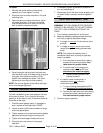
1. Remove right side panel as outlined under
"COVERS AND PANELS".
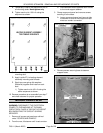
2. Pull insulation back to expose high limit
thermostat and disconnect lead wires.
3. Remove thermostat from heating element
assembly.


