


ELECTRICAL INSTALLATION
The appliance requires a 230 volt, 50Hz A.C. sup-
ply and the electrical installation must be carried
out by a qualified electrician in compliance with the
current regulations. This hob should be connected
to a double pole 32 Amp cooker box which is fitted
adjacent to the hob using a PVC insulated twin &
earth cable with conductor size of 6mm
2
.
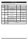
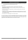
The terminal box is located on the underneath of
the hob and the power supply is connected to the
hob by ensuring the live supply is connected to
Terminal 1, the neutral to Terminal 5 and the earth
wire to the earth supply. The mains cable is
secured using the mains clamp.
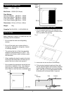
USING THE HOB FOR THE FIRST TIME
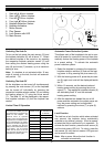
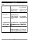
* Always use high quality pots with ideally flat
bottoms as it prevents points of too high tem-
perature forming on the bottom and conse-
quently sticking of the cooked food. Pots and
pans with thick metal sides guarantee perfect
distribution of heat.
* Avoid using cookware with aluminium or copper
bottoms as these can leave a metallic discol-
oration, which is very difficult to remove.
* Always ensure that the bottom of the pot is dry:
when you fill up the pot or take it out from the
fridge always check if the bottom is perfectly dry
as it helps to keep the plate clean.
* Always use pots matching the diameter of the
used heating element, the energy is most opti-
mally used if the diameter of the pot is slightly
bigger than the diameter of the hotplate.
* Lids prevent the heat from escaping from the
pot and thus shorten the cooking time and
reduce the consumption of power.
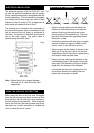
SELECTION OF COOKWARE
Before using the hob for the first time, thoroughly
clean the hob to ensure any debris is removed from
the surface of the hob that may cause damage to
the hob surface during operation. When using the
hob for the first time, the heating plates may emit a
light odour so it will be necessary to ventilate the
room in which the hob is located.
Fig.7
Note: Ensure that a link is present between
Terminals 1,2 & 3 and Terminals 4 & 5
respectively.
5
Fig.6