


5
WWW.WEBER.COM
®
5
1
1
1
2
a
2
a
3
4
5
6
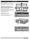
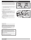
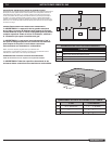
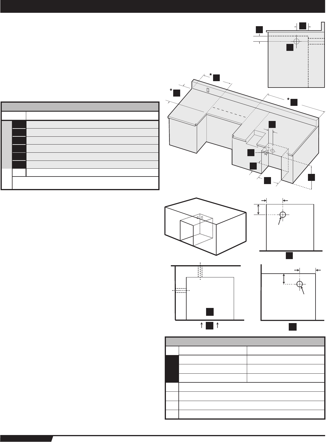
BUILT-IN GAS LINE LOCATIONS
GENERAL CONSTRUCTION DETAILS
• Summit
®
Built-In unit and all other accessory units should be on site before
construction begins.
• All dimensions have a tolerance of plus or minus (+/-)
1
/
4
inch (6.4mm).
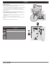
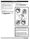
BUILT-IN GAS LINE LOCATIONS
Area should be kept clear of sharp, jagged, or extremely abrasive surfaces to avoid
possible damage to gas supply lines. Exercise caution when pulling gas lines through
built-in structure.
A
C
B
1
3
2
A
B
C
C
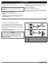
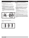
LP TANK CABINET GAS LINE DIMENSIONS
Area should be kept clear of sharp, jagged, or extremely abrasive surfaces to avoid
possible damage to gas supply lines. Exercise caution when pulling gas lines through
built-in structure.
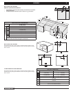
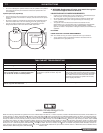
BUILT-IN CUTOUT DIMENSIONS
S-440, S-640
DIMENSIONS
1 24” (610 mm) minimum*
2 5” (127 mm)
3 2 1/2” (63.5 mm)
4 14” (355.6 mm)
5 20 3/4” (527.1 mm)
6 27 1/2” (698.5 mm)
a Gas Inlet
* Clearance from any surface or structure is at least 24” (610mm)
from the back and sides of the grill or side burner.
GAS LINE DIMENSIONS
TANK CABINET TOLERANCES
1 5” (127 mm) +
1
/
4
˝ -
1
/
4
˝ (6.35mm)
2 2 1/2” (63.5 mm) +
1
/
4
˝ -
1
/
4
˝ (6.35mm)
3 2 3/4” (69.85 mm) +
1
/
4
˝ -
1
/
4
˝ (6.35mm)
A Front View
B Plan View
C Side View
D Front of LP Tank Cabinate Structure
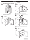
ASSEMBLY