-- 3 --
ASSEMBLY
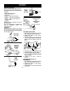
CARTON CONTENTS
Check carton contents against the fol-
lowing list. Refer to the illustrations in
the
OPERATION
section of this manual.
S
Nozzle
S
Elbow with spacer ring
S
Extension Tube (4)
S
Pivot Tube
S
Adapter -- gas units with tabs
S
Adapter -- electric units with tabs
S
Adapter -- electric units with tube
release button
S
Goggles
Examine parts for damage. Do not use
damaged parts.
If you need assistance or find parts mis-
sing or damaged, please call
1-800-554-6723.
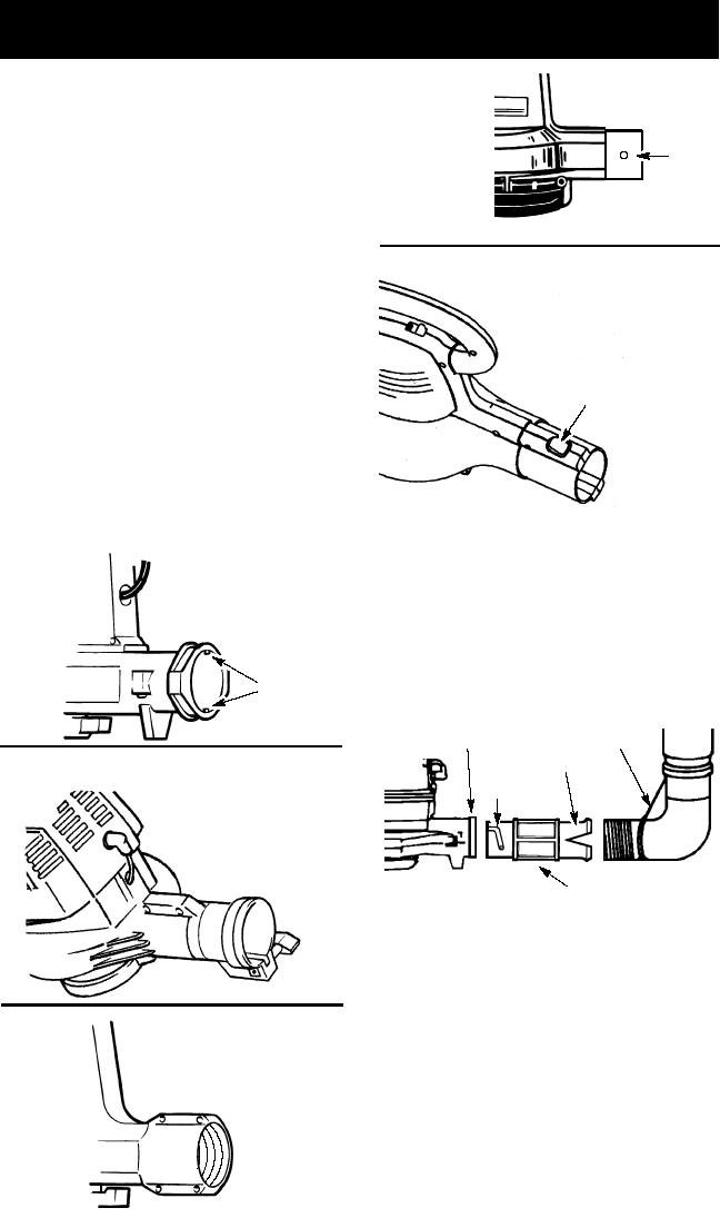
ASSEMBLY
Match the blower outlet on your unit to
oneofthose illustrated. Tobeginassem-
bly,go tothe section which corresponds
to your blower outlet.
Gas Units
with Tabs
Tabs
Gas Units
with Slot
&Clamp
Ring
Electric
Units
with
Threads
Electric
Units
with Tabs
Tabs
Electric Units
with
Tube Release
Button
Tube Release Button
GAS UNITS WITH TABS
1. Stop engine and wait until impeller
has completely stopped turning.
2. Remove all tubes or other attach-
ments from unit.
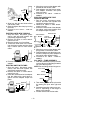
3. Insert the notched end ofthe adapter
into the elbow tube; push parts to-
gether until the adapter snaps into
place.
Elbow
Notched End
Groove
Blower Outlet
Adapter
4. Align thegrooves on the adapterwith
the tabs inside the blower outlet.
5. Insert theadapter into theblower out-
let; turn adapter clockwise until parts
snap into place.
6. Proceed to
ALL UNITS -- TUBE AS-
SEMBLY
.
GAS UNITS WITH SLOT &
CLAMP RING
1. Stop engine and wait until impeller
has completely stopped turning.
2. Remove all tubes or other attach-
ments from unit.
3. Thread spacer ring onto elbow threads
until secure.


