


INSTALLATION
4
READ THIS CAREFULLY BEFORE STARTING THE INSTALLATION
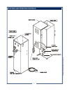
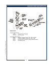
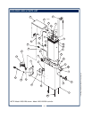
REFER TO EXPLODED VIEWS PAGE 14 FOR COMPONENT
NAMES/NUMBERS.
Unpack the unit. Inspect all components for completeness and
condition. Ensure that all packing materials have been removed
from the unit.
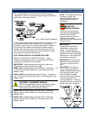
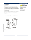
LEVELING THE UNIT
Two Gallon Dispenser is NOT provided with adjustable legs. Be
sure dispenser is placed on a solid level surface with all four feet
touching the surface.
Five Gallon Dispenser is provided with adjustable legs. Verify
that an adjustable leg is installed at each corner of the brewer.
Set Brewer in its operating location. Level the Brewer. A spirit
level should be placed on the top of the unit, at the edge, as a
guide when making level adjustments. Level the unit from left to
right and front to back by turning the adjustable feet. Be sure all
four feet touch the counter to prevent tipping.
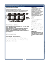
PLUMBER’S INSTALLATION INSTRUCTIONS
Dispenser should be connected to a POTABLE WATER, COLD
WATER line. Flush water line before connecting to appliance.
DO NOT use a saddle valve with a self-piercing tap for the water
line connection. Such a tap can become restricted by waterline
debris. For systems that must use a saddle tap, shut off the main
water supply and drill a 3/16” (minimum) tap for the saddle
connection, in order to insure an ample water supply. Remember
to flush the line prior to installing the saddle.
The dispenser must be installed on a water line with average
pressure between 20 PSI and 90 PSI. If your water pressure
exceeds 90 PSI at anytime, a pressure regulator must be
installed in the water supply line to limit the pressure to not more
than 90 PSI in order to avoid damage to lines and solenoid.
A water shut-off valve should be installed on the incoming water
line in a convenient location (Use a low restriction type valve,
such as a 1/4-turn ball valve, to avoid loss of water flow thru the
valve.
IMPORTANT:
To enable the installer to make
a quality installation and to
minimize installation time, the
following suggestions and tests
should be done before the
actual unit installation is started:
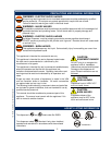
CAUTION:
EQUIPMENT DAMAGE
DO NOT plug in or energize this
appliance until all Installation
Instructions are read and
followed. Damage to the
dispenser will occur if these
instructions are not followed.
CAUTION:
UNSTABLE
EQUIPMENT HAZARD
It is very important for safety
and for proper operation that the
dispenser is level and stable
when standing in its final
operating position. Provided
adjustable, non-skid legs must
be installed at each corner of
the unit. Failure to do so will
result in movement of the
dispenser which can cause
personal Injury and/or damage
to appliance.
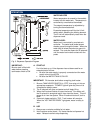
NOTE: Water supply inlet line
must meet certain minimum
criteria to insure successful
operation of the dispenser.
Bloomfield recommends 1/4"
copper tubing for installation of
less than 12 feet and 3/8" for
more than 12 feet from a 1/2"
water supply line.
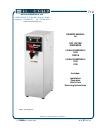
712 76580 Owners Manual Hot Water Dispenser