FIRE SUPPRESSION SYSTEM INSTALLATION
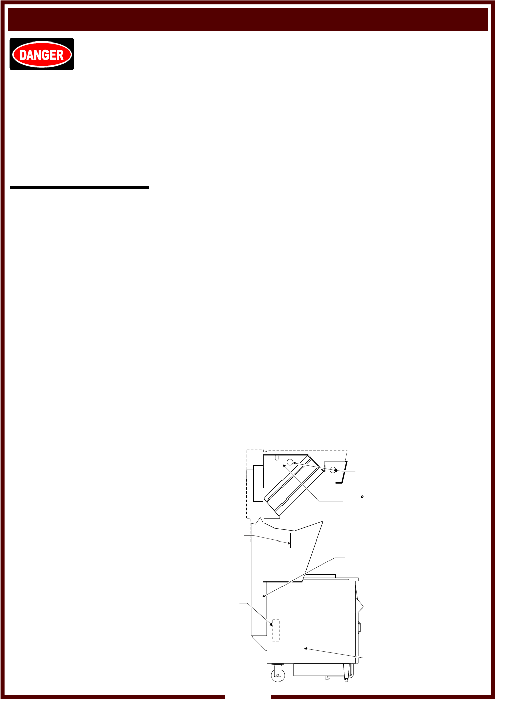
FIRE SUPPRESSION SYSTEM is comprised of a container of
Ansulex® Low pH liquid fire suppression media, a system
pressurization canister and associated plumbing and controls.
Two FUSIBLE LINKS are utilized for automatic actuation, and a
MANUAL PULL STATION for manual actuation. Two NOZZLES
disperse the fire suppression media.
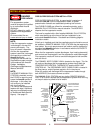
The hood is supplied with a field installed MANUAL PULL STATION,
which must be set-up at the time of the fryer installation by an
authorized Ansul® distributor. See below and following page for
installation details.
If the fryer is installed such that the supplied manual pull station cannot
be installed, a REMOTE MANUAL PULL STATION may be required by
local codes. Any such remote manual pull station must be installed by
an authorized Ansul® distributor in accordance with the AUTHORITY
HAVING JURISDICTION.
When the fire suppression system discharges, fryer heating element(s)
and controls are de-energized, and fire suppression media discharged.
Fire supression media will form an emulsion designed to both smother
and cool the oil.
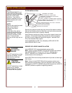
The PRIMARY 450ºF FUSIBLE LINK is located on the frypot. This link
will melt and discharge the fire suppression system should both the
TEMPERATURE CONTROL THERMOSTAT and the HIGH LIMIT
CONTROL fail. The SECONDARY 280ºF FUSIBLE LINK is located in
the filter plenum, and will protect against a fire in the plenum.
Either link melting will discharge the fire suppression media through
both NOZZLES, and cause a buzzer to sound.
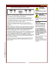
The MANUAL PULL STATION and any similar REMOTE MANUAL
PULL STATION will activate the fire suppression system when the ring
on the pull station is pulled to its full extent.
DANGER
FIRE HAZARD
Fire suppression system
must be charged and certified
by an authorized Ansul®
distributor.
DO NOT attempt to modify or
bypass the fire suppression
system.
An uncontrolled fire can
cause serious injury or death.
NOTE:
If the fire suppression system
is discharged, a buzzer will
sound continuously. The
fryer will remain inoperable
until the fire suppression
system is serviced, recharged
and reset by an authorized
Ansul® distributor.
Charging of the Ansul® Fire
Suppression system must be
in accordance with Ansul®
Design, Installation,
Recharge and Maintenance
Manual, #418087.
NOTE:
If a REMOTE MANUAL PULL
STATION is installed, moving
the FRYER for servicing may
cause the Ansul® system to
discharge. In this case, the
unit must only be installed
with four fixed legs
(i.e. remove rear casters and
replace with legs). Additional
legs may be ordered through
an Authorized Wells Service
Agency. See page 19.
INSTALLATION (continued)
8
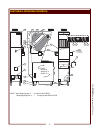
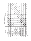
MANUAL PULL
STATION
INSTALLED
RIGHT OR LEFT
SIDE BY AN
AUTHORIZED
ANSUL®
DISTRIBUTOR
DURING
INITIAL
SET-UP
(ALL MODELS)
FIRE SUPPRESSION
AGENT DISPENSING
NOZZLE - 2 PLACES
APPROXIMATE
LOCATION OF
450 FUSIBLE
LINK (ALL
MODELS)
ALL MODELS REQUIRE
280 FUSIBLE
LINK
INSIDE
HOOD BEHIND
FILTERS
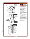
REMOVE PANEL
FOR ACCESS TO
FIRE SUPPRESSION
SYSTEM 450º
FUSIBLE LINK ON
WVAE-55 F/FS
REMOVE PANEL
FOR ACCESS TO
FRYPOT.
ALSO ACCESS TO
450 FUSIBLE
LINK ON WVAE-30F
AND WVPE-30F
º
º
M381 301603 OpM (Supplemental) NFPA Hood


