


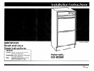
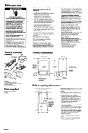
Before you start...
Electrical Shock Hazard
Contact a qualified electrical installer.
Assure that the electrical connection
is adequate and in conformance
with the National Electrical Code
ANSVNFPA 70 - latest edition* and
all local codes and ordinances.
Check that electrical wiring and
components Do Not contact any
plumbing material or drain hose.
Check that electrical wiring, water
supply line and drain line Do Not
contact any exposed terminals of the
ice maker wiring.
Check that electrical wiring is not
routed through drain area.
Check that plumbing and electrical
wiring Do Not cross in front of the ice
maker motor.
Install the ice maker in a cabinet that
completely encloses the sides, top
and rear of the ice maker.
Failure to follow these instructions
could result in death or serious injury.
Tools 81 materials
needed
A@
Not shown:
bucket, sponge, baking soda
1 -l/4” min. diameter standpipe or 5/W I.D.
minimum drain tube
l/4” O.D. soft copper tubing
Parts supplied
threaded compression fitting
ice scoop
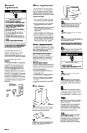
It is the customer’s responsibility to:
Observe all governing codes and
ordinances.
l
Comply with the installation
specifications and dimensions provided
l
Properly install the ice maker.
l
Make sure you have everything
necessary for correct installation.
l
Contact a qualified installer to assure
that the plumbing and electrical installa-
tions are adequate and meet all nation-
al and local codes and ordinances.
l
Provide a properly grounded outlet
(See “Electrical requirements.“)
l
Provide proper water supply line and
floor drain or drain pump, as specified.
(See “Water requirements” and “Drain
requirements.“)
Plumbing and electrical wiring should
not cross in front of the motor. Electrical
wiring should not be routed through the
drain area.
Read and follow the “Electrical
requirements, fl “Water requirements, II
and “Drain requirements, I before
installing the ice maker.
The ice maker may be enclosed around
the sides, top and rear. (See “Built-in
opening dimensions.“) Do Not block or
close in the front of the ice maker. The ice
maker cannot work properly if the airflow
to the front of the ice maker is blocked.
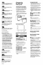
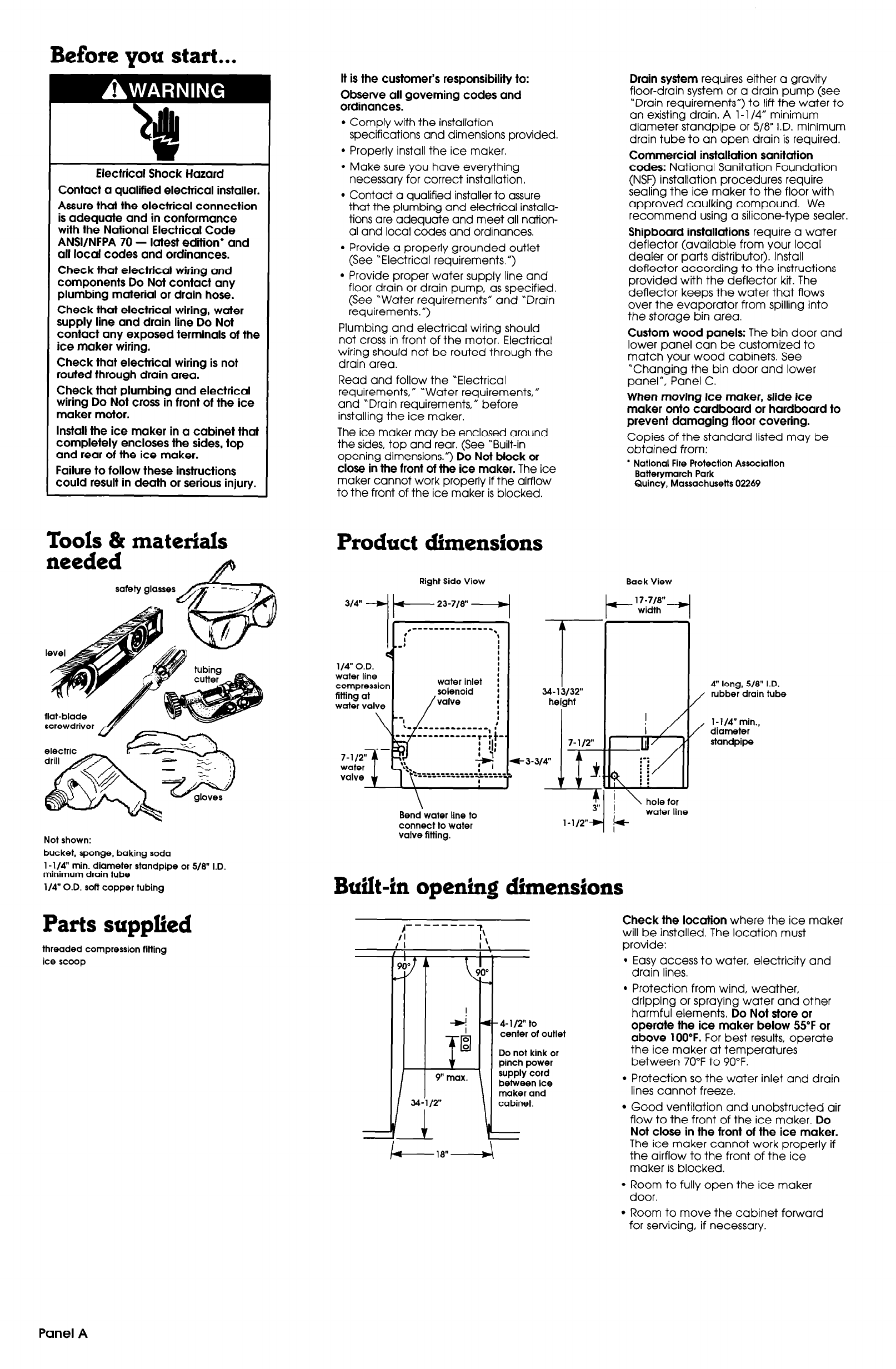
Product dimensions
314”
-I
Right Side View Bat k View
t 23-718”
+ 17:7/W
width
1WO.D. 1
i
water line
;
compression
water inlet ;
fitting at
solenoid
:
water valve
/ 1
valve
I
7-112” ,\
water
I’1
‘:.
valve
t
t===-.
Bend water line to
connect to water
valve fitting.
T
34- 13132”
height
Drain system requires either a gravity
floor-drain system or a drain pump (see
“Drain requirements”) to lift the water to
an existing drain. A l-l /4” minimum
diameter standpipe or 5/8” I.D. minimum
drain tube to an open drain is required.
Commercial installation sanitation
codes: National Sanitation Foundation
(NSF) installation procedures require
sealing the ice maker to the floor with
approved caulking compound. We
recommend using a silicone-type sealer.
Shipboard installations require a water
deflector (available from your local
dealer or parts distributor). Install
deflector according to the instructions
provided with the deflector kit. The
deflector keeps the water that flows
over the evaporator from spilling into
the storage bin area.
Custom wood panels: The bin door and
lower panel can be customized to
match your wood cabinets. See
“Changing the bin door and lower
panel”, Panel C.
When moving ice maker, slide ice
maker onto cardboard or hardboard to
prevent damaging floor covering.
Copies of the standard listed may be
obtained from:
l
National Fire Protection Association
Batterymarch Park
Quincy, Massachusetts 02269
! \ hole for
water line
Built-in opening dimensions
4” long, 518” I.D.
I/
rubber drain tube
/
1 -l/4” min.,
diameter
standpipe
rl
------_-
Check the location where the ice maker
/I
I\
will be installed. The location must
I I
I ‘,
provide:
,
I :
I
90” A
l
Easy access to water, electricity and
drain lines.
I
+ *-4-l/2” to
0
0
center of outlet
0
Do not kink or
pinch power
between ice
maker and
l
Protection from wind, weather,
dripping or spraying water and other
harmful elements. Do Not store or
operate the ice maker below 55°F or
above 100°F. For best results, operate
the ice maker at temperatures
between 70°F to 90°F.
l
Protection so the water inlet and drain
lines cannot freeze.
l
Good ventilation and unobstructed air
flow to the front of the ice maker. Do
Not close in the front of the ice maker.
The ice maker cannot work properly if
the airflow to the front of the ice
maker is blocked.
l
Room to fully open the ice maker
door.
l
Room to move the cabinet forward
for servicing, if necessary.
Panel A