


4. Remove all tape and packaging material from the
outside and inside of the cabinet. See Figure 4.
5. Remove the front grill; take out the screws securing
the grill at the bottom and lift it free of cabinet.
6. Turn the fan by hand to make certain it moves freely.
7. Loosen thumb screws holding cutter grid and water
pan to “thumb tight.”
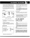
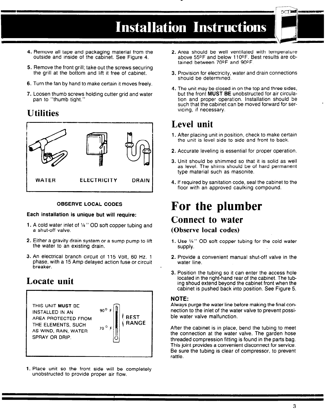
Utilities
WATER
ELECTRICITY
DRAIN
OBSERVE LOCAL CODES
Each installation is unique but will require:
1. A cold water inlet of l/4” OD soft copper tubing and
a shut-off valve.
2. Either a gravity drain system or a sump pump to lift
the water to an existing drain.
3. An electrical branch circuit of 115 Volt, 60 Hz.
1
phase, with a 15 Amp delayed action fuse or circuit
breaker.
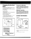
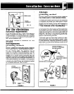
Locate unit
THIS UNIT MUST BE
INSTALLED IN AN
90’ F
AREA PROTECTED FROM
THE ELEMENTS, SUCH
AS WIND, RAIN, WATER
7OO.F
SPRAY OR DRIP.
1, BEST
\ RANGE
2. Area should be well ventilated with temperature
above 55OF and below 1 lOOF. Best results are ob-
tained between 7OOF and 9OOF.
3. Provision for electricity, water and drain connections
should be determined.
4. The unit may be closed in on the top and three sides,
but the front MUST BE unobstructed for air circula-
tion and proper operation. Installation should be
such that the cabinet can be moved forward for ser-
vicing, if necessary.
Level unit
1. After placing unit in position, check to make certain
the unit is level side to side and front to back.
2. Accurate leveling is essential for proper operation.
3. Unit should be shimmed so that it is solid as well
as level. The shims should be of hard permanent
type material such as masonite.
4. If required by sanitation code, seal the cabinet to the
floor with an approved caulking compound.
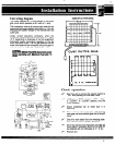
For the plumber
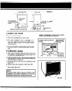
Connect to water
(0 bserve local codes)
1. Use l/4” OD soft copper tubing for the cold water
supply.
2. Provide a convenient manual shut-off valve in the
water line.
3. Position the tubing so it can enter the access hole
located in the right-hand rear of the cabinet. The tub-
ing shoud extend beyond the cabinet front when the
cabinet is pushed back into position. See Figure 5.
NOTE:
Always purge the water line before making the final con-
nection to the inlet of the water valve to prevent possi-
ble water valve malfunction.
After the cabinet is in place, bend the tubing to meet
the connection at the water valve. The garden hose
threaded compression fitting is found in the parts bag.
This joint provides a convenient disconnect for service.
Be sure the tubing is clear of compressor, to prevent
rattle.
1. Place unit so the front side will be completely
unobstructed to provide proper air flow.
3