


RIGHT END VIEW
3/4*-j I-- 23.7W~.
f-l
WATER INLET ’
I SOLENOID
‘E
VALVE
\ cy11
7,1/z- “\----_3-3’4” i-1
L ---
L
BEND FIELD SUPPilED WATER LINE
TO CONNECT TO WATER VALVE FITTING
l-l/Z”
BACK VIEW
FIGURE 5 ;
-17.7/w-c
1
t
4” LONG 5/S” I.D. RUBBER:
DRAIN TUBE - RUN TO
a
OPEN DRAIN
1
HOLE FOR FIELD
SUPPIED WATER
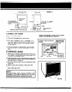
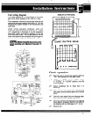
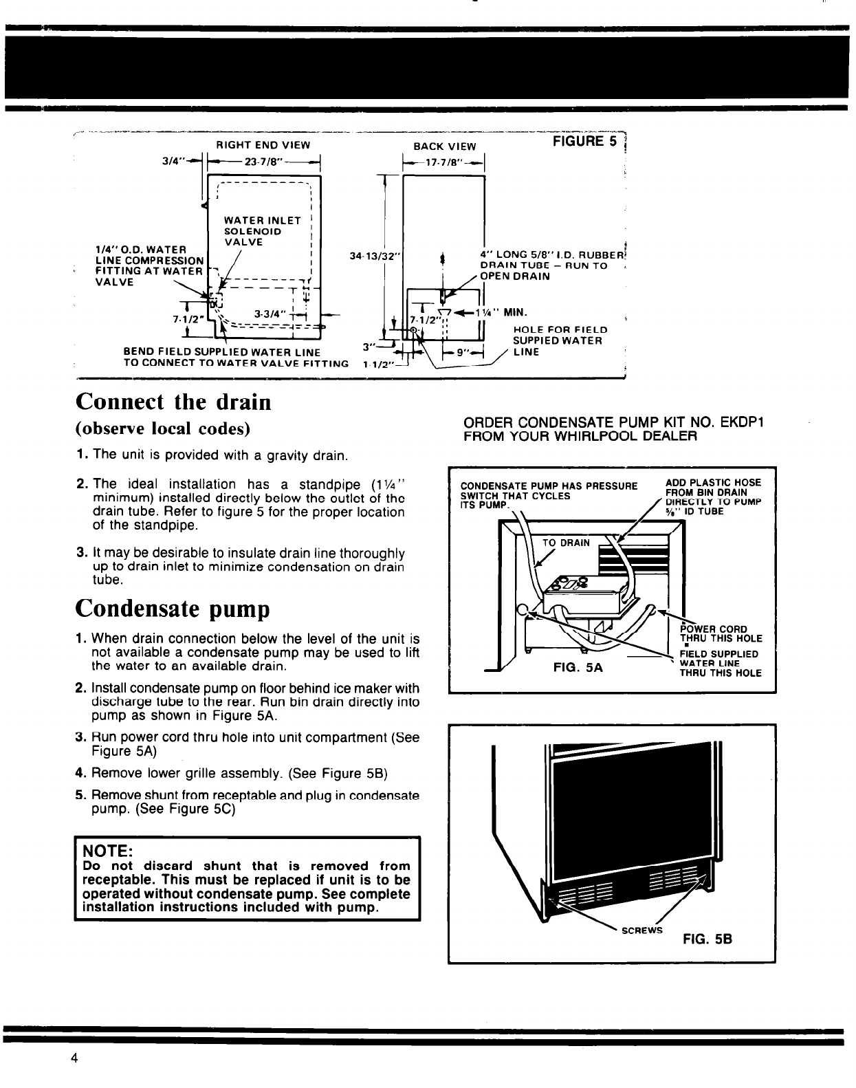
Connect the drain
(observe local codes)
1. The unit is provided with a gravity drain.
2. The ideal installation has a standpipe (1%”
minimum) installed directly below the outlet of the
drain tube. Refer to figure 5 for the proper location
of the standpipe.
3. It may be desirable to insulate drain line thoroughly
up to drain inlet to minimize condensation on drain
tube.
Condensate pump
1. When drain connection below the level of the unit is
not available a condensate pump may be used to lift
the water to an available drain.
2. Install condensate pump on floor behind ice maker with
discharge tube to the rear. Run bin drain directly into
pump as shown in Figure 5A.
3. Run power cord thru hole into unit compartment (See
Figure 5A)
4. Remove lower grille assembly. (See Figure 58)
5. Remove shunt from receptable and plug in condensate
pump. (See Figure 5C)
Do noi discard shunt that is removed from
ORDER CONDENSATE PUMP KIT NO. EKDPl
FROM YOUR WHIRLPOOL DEALER
CONDENSATE PUMPHASPRESSURE
ADD PLASTIC HOSE
SWITCH THAT CYCLES
FROM BIN DRAIN
CTLY TO PUMP
’ SCREWS
FIG. 58
4