


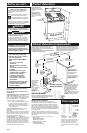

Operating position
C
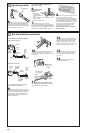
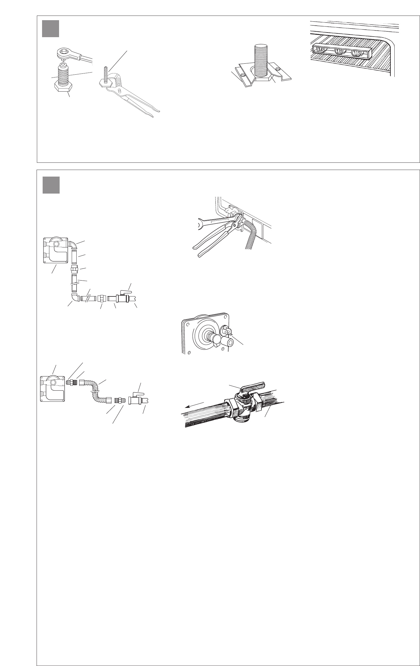
5.Remove cardboard shipping base from
under range. Remove storage drawer. Use a
3/8” drive ratchet to lower rear leveling legs
one-half turn. Use channel lock pliers to lower
front leveling legs one-half turn.
6.Making sure the
anti-tip bracket is
installed:
• Look for the
anti-tip bracket
securely attached to
floor.
• Slide range back so rear range foot is under
anti-tip bracket.
Replace storage drawer.
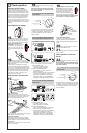
7. If installing the range in a mobile
home, you MUST secure the range to the floor.
Any method of securing the range is adequate as
long as it conforms to the “Manufactured Home
Construction and Safety Standard,” Page 2.
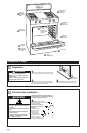
8.Place rack in oven. Place level on rack,
first side to side; then front to back.
If range is not level, pull range forward until
rear leveling leg is removed from the anti-tip
bracket. Use 3/8" drive ratchet and channel
lock pliers to adjust leveling legs up or down
until range is level. Push range back into
position. Check that rear leveling leg is
engaged in anti-tip bracket.
Note: Oven must be level for satisfactory
baking conditions.
Page 5
Before moving range across floor, check that
range is still on cardboard shipping base to
protect floor covering.
rear leveling leg
front leveling leg
anti-tip
bracket
range foot
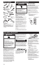
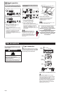
Gas and electrical connections
D
9.Apply pipe-joint compound made for
use with L. P. gas to the smaller thread ends of
the flexible connector adapters. Attach one
adapter to the pressure regulator elbow and
the other adapter to the gas shutoff valve.
Tighten both adapters.
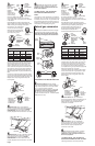
11. Check that range regulator shutoff
valve is in the “on” position. Open the manual
shutoff valve in the gas supply line.
13.Center the burner cap on burner
base. Burner cap should be level when
properly positioned. Place burner grates
over burner.
14.Plug power supply cord into
grounded electrical outlet.
12.Use a brush and liquid detergent
to test all gas connections. Bubbles around
connections will indicate a leak. If a leak
appears, shut off gas valve controls and
tighten connections. Then check connections
again. Clean all detergent from range.
All connections must be wrench-tightened.
10.Use 15/16" combination wrench and
channel lock pliers to attach the flexible
connector to the adapters. Check that connector
is not kinked.
90˚elbow
1/2" to 3/4"
gas pipe
nipple
nipple
adapter
adapter
manual
gas
shutoff
valve
manual
gas
shutoff
valve
black iron
pipe
A 1/2" male pipe thread is needed for connection to
pressure regulator female pipe threads.
union
union
pressure
regulator
90˚elbow
1/2" to 3/4"
gas pipe
pressure
regulator
Typical rigid pipe connection
Typical flexible connection
flexible
connector
use pipe-joint
compound
use pipe-joint
compound
manual shutoff valve
“open” position
regulator shutoff
valve in “on”
position
gas supply
to range