


3
INSTALLATION REQUIREMENTS
Tools and Parts
Gather the required tools and parts before starting installation.
Read and follow the instructions provided with any tools listed
here.
Tools needed
Parts supplied
Check that all parts are included.
■ 2 - #8 x ¹⁄₂" screws
■ Trim plate
■ 2 - Oven racks
■ 2 - #12 x 1⁵⁄₈" mounting screws (for mounting anti-tip bracket)
■ Anti-tip bracket (taped to oven rack)
Parts needed
■ A UL listed or CSA approved conduit connector
■ UL listed wire connects
Check local codes. Check existing electrical supply. See
“Electrical Requirements” section.
It is recommended that all electrical connections should be made
by a licensed, qualified electrical installer.
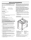
Location Requirements
IMPORTANT: Observe all governing codes and ordinances.
■ It is the installer’s responsibility to comply with installation
clearances specified on the model/serial rating plate. The
model/serial rating plate is located below the electronic
control on oven frame.
■ The range should be located for convenient use in the
kitchen.
■ To eliminate the risk of burns or fire by reaching over heated
surface units, cabinet storage space located above the
surface units should be avoided. If cabinet storage is to be
provided, the risk can be reduced by installing a range hood
that projects horizontally a minimum of 5" (12.7 cm) beyond
the bottom of the cabinets.
■ Cabinet opening dimensions that are shown must be used.
Given dimensions are minimum clearances.
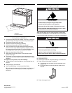
■ The floor anti-tip bracket must be installed. To install the anti-
tip bracket shipped with the range, see “Install Anti-Tip
Bracket” section.
■ Range support slats must be solid, level and flush with
bottom of cabinet cutout. Floor must be able to support a
weight of 225 lbs (102.0 kg). Support slats must be securely
fastened to the floor.
■ Recessed installation area must provide complete enclosure
around the recessed portion of the range.
■ Grounded electrical supply is required. See “Electrical
Requirements” section.
IMPORTANT: To avoid damage to your cabinets, check with your
builder or cabinet supplier to make sure that the materials used
will not discolor, delaminate or sustain other damage. This oven
has been designed in accordance with the requirements of UL
and CSA International and complies with the maximum allowable
wood cabinet temperatures of 194°F (90°C).
Mobile Home - Additional Installation Requirements
The installation of this range must conform to the Manufactured
Home Construction and Safety Standard, Title 24 CFR, Part 3280
(formerly the Federal Standard for Mobile Home Construction
and Safety, Title 24, HUD Part 280). When such standard is not
applicable, the Standard for Manufactured Home Installations,
ANSI A225.1/NFPA 501A or with local codes.
Mobile home installations require:
■ When this range is installed in a mobile home, it must be
secured to the floor during transit. Any method of securing
the range is adequate as long as it conforms to the standards
listed above.
■ Four-wire cable must be used in a mobile home installation.
The appliance wiring will need to be revised. See “Electrical
Connection” section.
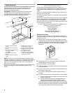
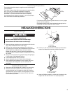
Product Dimensions
*Range can be raised approximately 1" (2.5 cm) by adjusting
the leveling legs.
**When installed in a 24" (61.0 cm) base cabinet with
25" (63.5 cm) countertop; front of oven door protrudes 2¹⁄₂"
(6.4 cm) beyond 24" (61.0 cm) base cabinet.
■ Tape measure
■ Level
■ Phillips screwdriver
■ Flat-blade screwdriver
■ Wrench or pliers
■ Hand or electric drill
■ ¹⁄₈" (3.2 mm) drill bit
A. 30³⁄₄" (78 cm)
B.27¹⁄₂" (69.9 cm) height to underside
of cooktop edge with leveling legs
screwed all the way in*
C. Model/serial number plate
(located below the electronic
control on oven frame)
D. 29⁷⁄₈" (75.9 cm)
E. 28⁵⁄₁₆" (71.9 cm) from
handle to standoff at back
of range**
F. 2 3 ³⁄₄" (60.3 cm)
countertop notch to rear
of cooktop
C
B*
A
D
E**
F