


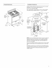

8. Movetherangeclosetotheopening.Removetheshipping
base,cardboardorhardboardfromundertherange.
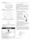
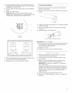
9.Openthebroilerdoor.Usea3/8"driveratchettolowerthe
rearlevelinglegsone-halfturn.Useflip-jointplierstolower
thefrontlevelinglegsone-halfturn.
10.Adjusttheleveling
legstothecorrect
height.Levelinglegscanbeloosenedtoadduptoamaxi-
mumof1"(2.5cm).Aminimumof3/16"(5mm)isneededto
engagetheanti-tipbracket.
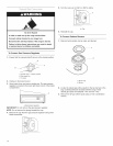
11.Movetherangeintofinalpositionmakingsuretherearlevel-
inglegslidesintotheanti-tipbracket.
12.Ifinstallingtherangeinamobilehome,youmustsecurethe
rangetothefloor.Anymethodofsecuringtherangeisade-
quateaslongasitconformstothestandardsinthe
"LocationRequirements"section.
13.Continueinstallingyourrangeusingthefollowinginstallation
instructions.
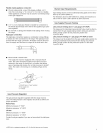
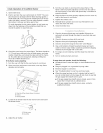
1.Makesuretheanti-tipbracketisinstalled:
[] Lookfortheanti-tipbracketsecurelyattachedtothefloor.
[] Slidetherangebacksotherearrangefootisundertheanti-tip
bracket.
2.Ifinstallingtherangeinamobilehome,youmustsecurethe
rangetothefloor.Anymethodofsecuringtherangeisade-
quateaslongasitconformstothestandardsinthe"Location
Requirements"section.
3.Ifrangeisnotlevel,pullrangeforwarduntilrearlevelinglegis
removedfromtheanti-tipbracket.Uses/8"driveratchetand
slip-jointplierstoadjustlevelinglegsupordownuntilrangeis
level.
4.Pushrangebackintoposition.
5.Checkthatrearlevelinglegisengagedinanti-tipbracket.
NOTE:Rangemustbelevelforsatisfactorybakingperformance.
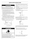
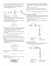
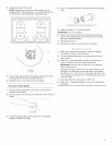
Typicalrigidpipeconnection
Acombinationofpipefittingsmustbeusedtoconnecttherange
totheexistinggasline.Yourconnectionmaybedifferent;accord-
ingtothesupplylinetype,size,andlocation.
t. ApplypipejointcompoundmadeforusewithLPgastoall
pipethreadconnections.
2. Usingapipewrenchtotighten,connectthegassupplytothe
range.
_ _ ....................S
H
G .....................
F
L,J
A. Pressure regulator con- D. Union
nection tiffing E.Nipple
B. 90°elbow E Manual shutoff valve
C. Black iron pipe G. V2"to 3A"gas pipe
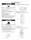
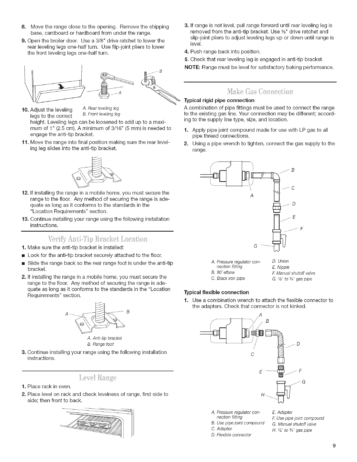
Typical flexible connection
t. Use a combination wrench to attach the flexible connector to
the adapters. Check that connector is not kinked.
A
A.Anti-tipbracket
B.Rangefoot
3. Continue installing your range using the following installation
instructions.
1. Place rack in oven.
2. Place level on rack and check levelness of range, first side to
side; then front to back.
E .............. _ .........................F
G
b.J
A. Pressure regulator con-
nection tiffing
B. Usepipe joint compound
C. Adapter
D. Flexible connector
E.Adapter
E Use pipe joint compound
G. Manual shutoff valve
H. V2"to 3/4'_gas pipe