


INSTALLATION
REQUIREMENTS
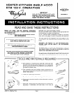
A. Space Requirements
A typical installation can be seen in Figure 1. Study Figure 1
before proceeding. The shelf hood requires an opening that
is 30” wide. It is recommended that the cabinet above the
cooktop be a maximum of 15” high. This provides the
adequate space btween the range cooktop and the shelf
hood.
B. Electrical Requirements
A 120 Volt, 60 Hz, AC only, 20Ampere fused electrical supply
is required (Time delay fuse or circuit breaker is
recommended). It is recommended that a separate circuit
serving only this appliance be provided.
VENTING REQUIREMENTS
Before you begin, determine where the ductwork will run.
For best performance, keep the length of ductwork and the
number of elbows to a minimum.
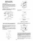
Illustrated are some of the more common methods. (Figures
2,3. and 4).
IMPORTANT: THE VENTING SYSTEM MUST TERMINATE
TO THE OUTSIDE. DO NOT TERMINATE THE VENT IN AN
ATTIC OR OTHER ENCLOSED SPACE. THIS MAY RESULT
IN A FIRE HAZARD.
ROOF CAP
Figure 2
TRANSITION-
3% X 10 THRU WALL
(8.3 X 25.4 cm)
Figure 3
IMPORTANT: WALL AND ROOF CAPS MUST HAVE BACK-
DRAFT DAMPER.
NOTE: Ductwork, wall and roof caps not supplied with hood.
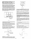
3%” X 10 to ROUND (7” MIN. DIAMETER)
THRU ROOF
Figure 4
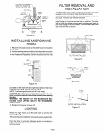
INSTALLATION
1. Select the area for installation, making sure you have an
electrical supply available. See the shaded area (Figure 5).
This is the area the electrical supply must enter.
ELECTRICAL
ROUGH-IN AREA
\
-USE LEVEL-
Figure 5
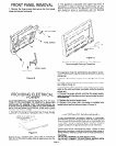
CAUTION: Due to the amount of weight the shelf hood
mUSt
support, make sure the hood is mounted to two vertical 2x4
wall studs with the four lag bolts and into the wall covering
(I/Z” sheet rock minimum) with the four anchor bolts. Lag
bolts and anchor bolts (eight in all) are supplied in the Inslal-
lation Assembly.
2. If the shelf hood is mounted to a wall that does NOT meet
the above recommendations, the weight of the microwave
oven may cause the hood to pull away from the wall resulting
in personal injury or property damage.
3. Mark a line on
the
back wall 15” down from the upper
cabinets centered between the side cabinets or the allotted
space. Use a level. (Figure 5).
Page 2