,WIRING DONE ACCORDING TO
NATIONAL ELECTRICAL CODE
AND APPLICABLE LOCAL CODES1
RECEPTACLE
TERMINAL
ACCESS
COYER
Figure 13
FILTER CLIPS
INSTALLING MICROWAVE
OVEN
1. Place the microwave oven on the shelf hood in the center
of the hood.
2. Use the leveling bolts provided to level the shelf hood after
the weight of the appliance is placed on it. Bolts are provided
in the installation Assembly. Screw the bolts into the nuts
Figure 14
provided on the lower left and right hand sides of the hood
until the unit is level. (Figure 14) Use
a
level.
NOTE: The leveling bolts have a 9116” Hex Head.
CAUTION: The mlcrowave oven must be level from front to
back to minimize utensils from sliding forward when openlng
the door.
WARNING: THE WEIGHT OF THE MICROWAVE MAY
EXCEED YOUR LIFTING ABILITY. WE RECOMMEND
ASSISTANCE.
3. Replace front panel. (Figure 10)
LIGHTING
Select two light bulbs up to 60 watts each to achieve the
desired lighting.
The bulbs may be installed or removed by removing the filter.
FILTER REMOVAL AND
INSTALLATION
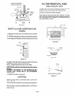
The aluminum filter is held in place with the two filter clips
located on the front panel. (See illustrations below).
To remove the filter, simply turn the filter clips to the front of
the hood. The filter can now be removed.
To replace the filter, place one end of the filter beneath the
back flange of the panel and set filter in position. The filter
will set over the blower housing with the other end flush on
the lower flange of the front panel. Turn the filter clips to the
rear until the filter is secure.
FILTER INSTALLED
Figure 15
FILTER CLIP / -~ -\ FRONT
Figure 16
BLOWER
HOUSING
F’LTER
FILTER INSTALLATION
Figure 17
Once the filter is removed, adequate space is provided on
either side of the filter area for installation or removal of the
bulbs by hand.
Page 5


