


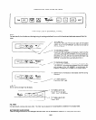

TRAIN CAP
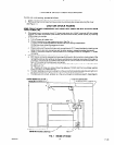
1.
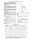
Make a template or transfer measurements shown in Fig. 3
to cabinets or wall.
2. Cut holes to accomodate ventilating duct allowing W’ (.6
cm) clearance on all four sides for back vent. Allow J/4” (1.9
cm) clearance toward front for vertical vent. Allow %” (.6 cm)
on other three sides for top vent.
3. Cut appropriate hole for electrical wiring.
4. Run wire through wall or cabinets according to National
Electrical Code and Applicable local codes. (DO NOT turn
power on until installation is complete.)
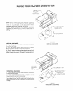
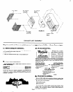
5. Remove blower housing and filters for easier installation.
See exhaust unit assembly illustration on page 6.
6. Remove screw holding junction box cover.
7. Remove proper electrical knockout. See Figure 3.
8. Remove proper venting knockout. See Figure3. NOTE: If
horizontal discharge is selected an additional knockout in
the blower cradle must be removed.
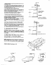
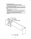
9. Attach the damper as shown in Figure 5 for vertical
discharge or Fig. 6 for horizontal discharge.
10. Lift the hood into position. Mark location of four mounting
holes.
11. Remove hood and start all four screws in center of
narrow neck of keyhole slot marked on cabinet bottom.
12. Lift the hood into position simultaneously feeding the
electrical wire through the knockout. Follow applicable local
codes and/or latest National Electrical Code for electrical
connector to be used at field wiring entrance.
13. Tighten screws to secure hood. Be sure screw head is in
narrow neck of keyhole slot.
14. Install proper duct work. See page 4
15. Complete electrical wiring in junction box according to
the National Electrical Code and applicable Local Codes
NOTE: This unit must be permanently grounded in
accordance with the National Electrical Code and applicable
Local codes.
16. Replace junction box cover.
17. Replace blower. Note different blower positions in
Figure 5 for vertical venting and Figure 6 for horizontal
venting. See Page 3 for correct blower installation.
18. Replace blower cover, light frame assembly and filters.
NOTE: It has been found that a large part of the energy loss
of the average home is due to outside air infiltrating the
structure. Seal around ductwork where it passes through
outside walls or ceiling. Seal around electrical wiring also.
19.
Be sure that damper which is supplied with this model is
properly installed. (See Figures 1 8 2).
6-1
FIG&E 5
IF RAIN CAP HAS
A CAMPER, REMOVE
DAMPEF) BLADE
FROM rCOO0
FIGURE 1
VERTICAL VENTING
,a
3%. x IO” RECTANGULAR
IF RAIN CAP HAS
A DAMPER. REMOVE
DAMPER BLAOE
FROM HOOD.
FIGURE 2
HORIZONTAL VENTING
c5mf
FIGURE 6
FIGURE 4
Page 2