


FULL SIZE GAS CONVECTION OVENS - ELECTRICAL OPERATION
F32700 (February 2006)Page 35 of 64
SEQUENCE OF OPERATION
WKG, WKGX With Roast & Hold Option
(Mechanical KX Thermostat)
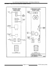
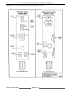
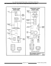
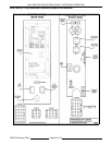
Schematic diagram 10832 will be used to explain the
electrical sequence of operation for both the Normal
ROAST cycle (normal cooking) and the ROAST &
HOLD cycle.
Normal Roast Cycle
1. Conditions.
A. Oven connected to correct voltage.
1) L1 (HOT) to power switch (S1).
2) L2 (NEUTRAL or SECOND LINE) to
one side of the following components:
power ON light, heat light, oven cavity
lights, buzzer, ROAST timer motor
(normal cooking), ROAST & HOLD
timer motor, heat relay coil (R3),
convection fan motor common (C),
transformer primary (T1), relay coil
(R4), motor speed (Hi/Low) relay coil
(R1), hold relay coil (R2) and the
component cooling fan.
B. Oven properly grounded.
C. Gas supply valve ON.
D. Gas combination control valve ON.
E. Power switch (S1) OFF.
F. Function switch (S3) set to Normal ROAST
cycle.
G. Oven light switch (S2) ON/OFF (position
has no affect on the function of the Normal
ROAST cycle).
H. Control thermostat dial in the OFF position
(OPEN).
I. High limit switch CLOSED.
J. Roast timer (normal cooking) in the OFF
position.
K. Roast and Hold timer in the OFF position.
L. Oven doors CLOSED.
1) Door switch contacts CLOSED.
M. Oven cavity temperature below 140°F.
2. Set thermostat to desired Normal ROAST
temperature (normal cooking).
A. Internal contacts close.
3. Power switch (S1) turned ON.
A. Power to motor speed (Hi/Low) relay (R1)
normally open (N.O.) contacts and hold
relay (R2) common (C).
B. Component cooling fan energized.
C. Power ON light (Amber) comes ON.
D. Power to one side of the following
components: Normal ROAST timer
terminal 1, ROAST & HOLD timer terminal
1, transformer primary (T1).
NOTE: Power is available to the oven light
switch (wire #20) to turn the oven cavity
lights ON when the light switch is turned
ON; and power is available to the normally
open N.O. side (wire #28) of the door
switch contacts and connects power to
additional components when the door
switch contacts are CLOSED (door
closed).
1) Transformer (T1) energized.
a. Power (24VAC) to one side of
the following components: heat
relay (R3) normally open (N.O.)
contacts, high limit --- connected
through the normally closed
(N.C.) contacts to the 1
st
valve
(safety) on the dual solenoid gas
valve.
a) 1
st
valve (safety) on the gas
valve energized.
NOTE: Gas does not flow to the
burner until the 2
nd
valve (main)
is energized.
2) With door switch closed, power is
connected back through a second set
of contacts on the power switch (S1),
through the thermostat contacts,
through one set of relay R4 normally
closed (N.C.) contacts, to one side of
the centrifugal switch on the
convection fan motor.
a. Heat light (clear) comes ON.
3) Power is also connected through the
other set of relay R4 normally closed
(N.C.) contacts to the other side of
motor speed relay (R1).
a. Motor speed relay (R1)
energized, contacts change state
and the normally open (N.O.) set
of contacts close.
a) Power is connected through
the function switch (S3)
contacts and the convection
fan motor is energized (fan
speed Hi).