


FULL SIZE GAS CONVECTION OVENS - ELECTRICAL OPERATION
F32700 (February 2006) Page 44 of 64
2. Power Switch (S1) turned to OVEN COOL.
NOTE: With door switch contacts OPEN (doors
open), the convection fan motor will still run and
continue to cool the oven. However, power would be
removed from the following components: Power ON
light (goes out), Normal ROAST timer, ROAST &
HOLD timer, transformer T1 (de-energized) and to
the component cooling fan.
A. Power to motor speed (Hi/Low) relay (R1)
normally open (N.O.) contacts and to
common (C) on hold relay (R2). Power is
then connected through hold relay (R2)
normally closed (N.C.) contacts to motor
speed (Hi/Low) relay (R1) coil.
1) Motor speed (Hi/Low) relay (R1) is
energized and contacts change state.
a. Power is connected through
motor speed (Hi/Low) relay
normally open (N.O.) contacts,
through function switch (S3) to
Convection fan motor.
a) Convection fan motor
energized.
NOTE: If function switch (S3) is
set to Normal ROAST cycle, fan
speed will be high; if set to
ROAST & HOLD cycle, fan
speed will be low.
b) When Convection fan motor
reaches operating speed the
centrifugal switch on the
motor closes but no power
is available for connection to
other components.
B. Power to one side of the hold thermostat
contacts but is not transferred to other
components due to oven cavity
temperature above 160°F (thermostat
OPEN).
C. Power to terminal 7 on the solid state
temperature control but is not transferred
to other components due to temperature
control not being powered.
3. If door switch is CLOSED (doors closed), power
is supplied to one side of the following
components: Power ON light (Amber), oven
light switch (S2), Normal ROAST timer terminal
1, ROAST & HOLD timer terminal 1,
transformer primary (T1) and component
cooling fan.
1) Power ON light (Amber) comes ON.
2) Transformer (T1) energized.
a. Power (24VAC) to one side of
the following components: heat
relay (R3) normally open (N.O.)
contacts, high limit --- connected
through the normally closed
(N.C.) contacts to the 1
st
valve
(safety) on the dual solenoid gas
valve.
a) 1
st
valve (safety) on the gas
valve energized.
NOTE: Gas does not flow to the
burner until the 2
nd
valve (main)
is energized.
3) Component cooling fan.
4. The oven will remain in this condition until the
power switch (S1) is turned to the OFF or ON
position.
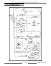
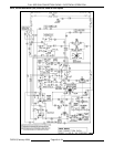
WKGC, WKGCX
(Roast & Hold Standard on Computer Model)
Schematic diagram 10835 will be used to explain the
electrical sequence of operation for both the ROAST
cycle (normal cooking) and the ROAST & HOLD
cycle.
Roast Cycle (Normal Cooking)
1. Conditions.
A. Oven connected to correct voltage.
1) L1 (HOT) to power switch (S1).
2) L2 (NEUTRAL or SECOND LINE) to
one side of the following components:
oven cavity lights, convection fan
motor common (C), transformer
primary (T1), component cooling fan
and the heat relay coil (R1).
B. Oven properly grounded.
1) Ground (GND) to one side of the
following components: computer
control case, NO IGNITION light,
transformer secondary (T1), ignition
control module, the 1
st
valve (safety)
and 2
nd
valve (main) on the dual
solenoid gas valve and computer
control pin 9 (C3-9).
C. Gas supply valve ON.
D. Gas combination control valve ON.
E. Power switch (S1) OFF.
F. Computer control is setup properly and
ready to use.
G. Oven light switch (S2) ON/OFF (position
has no affect on the function of the ROAST
cycle).
H. High limit switch CLOSED.