


4
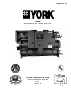
YORK INTERNATIONAL
GENERAL
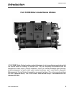
The Liquid Chiller will be completely assembled with all
interconnecting refrigerant piping and internal wiring,
ready for field installation.
The unit will be pressure-tested, evacuated, and charged
with Refrigerant-22, and York ‘L’ (POE) synthetic oil.
There will be an operational test, with water flowing
through the cooler, to check that each control device
operates correctly.
The unit will be covered with a coat of Caribbean Blue
enamel. Units are designed in accordance with NFPA
70 (National Electric Code), U.L. and cU.L. Standards,
ASHRAE/ANSI 15 Safety Code for Mechanical Refrig-
eration. All units are produced at an ISO 9001 regis-
tered facility. All YCWS chillers are rated and certified in
accordance with ARI Standard 550/590 at ARI condi-
tions.
SEMI-HERMETIC YORK SCREW COMPRESSORS
• Continuous function, microprocessor controlled, 3- way
proportional Capacity Control Valve provides regulated
output pressure independent of valve input pressure
for a stable, smooth, and precise match of compres-
sor capacity to cooling load to 10% of chiller capacity.
• Automatic spring return of capacity control valve to
minimum load position ensures compressor starting
at minimum motor load. Internal discharge check to
prevent rotor backspin upon shutdown.
• Acoustically tuned, internal discharge gas path elimi-
nates objectionable noise at the source, while optimiz-
ing flow for maximum performance.
• Reliable suction gas cooled, high efficiency, acces-
sible hermetic motor with APT2000 type magnet wire
and redundant overload protection using both ther-
mistor and current overload protection.
• Suction gas screen and serviceable, 0.5 micron full
flow oil filter within the compressor housing.
• Cast iron compressor housing precisely machined for
optimal clearances and superb efficiency. Entire com-
pressor, from suction to discharge has a Design Work-
ing Pressure of 450psig (31 bar).
• 350W compressor body cartridge heater.
• Each compressor will be mounted on isolator pads to
reduce transmission of vibration to the rest of the unit.
COOLER
The dual-circuit cooler will be the direct-expansion type,
with refrigerant in the tubes and chilled liquid flowing
through the baffled shell. The design working pressure
of the shell (liquid) side will be 150 PSIG (10.3 bar), and
300 PSIG (26.7 bar) for the tube (refrigerant) side.
The cooler will be constructed and tested in accordance
with the applicable sections of the ASME Pressure Ves-
sel Code, Section VlII, Division (1). The water side will
be exempt per paragraph U-1, (c)(6).
The water baffles will be constructed of galvanized steel
to resist corrosion. The removable heads will allow ac-
cess to the internally enhanced, seamless, copper tubes.
Vent and drain connections will be included.
The cooler will be covered with 3/4" (19.1 mm ) flexible,
closed-cell, foam insulation (K = 0.25).
CONDENSER
The condenser is a cleanable thru-tube type with steel
shell, copper tubes, removable water heads, and includes
integral subcooling. Refer to PHYSICAL DATA for de-
sign working pressures. The shell will be constructed
and tested in accordance with section Vll, division 1 of
the ASME pressure-vessel code. The water side is ex-
empt per paragraph U-1 (c) of section VlII, division 1 of
the ASME pressure-vessel code. The condenser is
equipped with relief valves and will hold the full refriger-
ant charge for pumpdown.
REFRIGERANT CIRCUIT
Two independent refrigerant circuits will be furnished on
each unit. All piping will be copper with brazed joints.
The liquid line will include: a shutoff valve with charging
port; sightglass with moisture indicator; thermal expan-
sion valve; solenoid valve; and high-absorption remov-
able-core filter drier. The entire suction line and the liq-
uid line between the expansion valve and the cooler will
be insulated with flexible, closed-cell, foam insulation.
POWER AND CONTROL PANELS
All controls and motor starting equipment necessary for
unit operation shall be factory wired and function tested.
The panel enclosures shall be designed to NEMA 1 (IP
32) and manufactured from powder-painted galvanized
steel.
Specifications