


46
YORK INTERNATIONAL
UNIT LOCATION
Chillers may be placed on the ground floor or upper floor
of the building. The floor must be level and capable of
supporting 150% of the operating weight of the unit. Units
should be located away from noise-critical areas. Ser-
vice clearance must be allowed and include space for
removing cooler or condenser tubes. A doorway or win-
dow can sometimes provide space for tube removal.
Units should be installed indoors where they are not ex-
posed to rain or water splash. Chillers should be located
near a drain. The use of chillers in corrosive, dusty or
explosive atmospheres should be avoided unless the
unit is properly protected. A unit located in a clean room
will run best, require least maintenance, and last long-
est. Heat or ventilation may be required to maintain the
ambient between 40°F and 115°F (4.4°C and 46.1°C).
UNIT ISOLATION
The chiller foundation must be rigid to reduce vibration
transmission to a minimum. All upper story installations
should use vibration isolators under the unit base. To
maintain isolator efficiency, no mechanical ties should
be made to the building. Properly selected flexible con-
nectors and piping isolators are recommended. All the
above recommendations will help to reduce vibration
transmission and result in a quieter operation.
FIELD CONNECTED WATER PIPING
Piping must comply in all respects with applicable local
plumbing codes and ordinances. In no case should the
unit support the weight of connecting piping. Since el-
bows, tees, and valves increase pressure drop, all pip-
ing should be kept as simple as possible. Hand stop
valves should be installed where required to facilitate
servicing. Piping to the inlet and outlet connections of
the cooler and condenser may include high-pressure
rubber hose or piping loops to ensure against water pump
transmission of vibration.
Facilities should be provided for measuring temperature
and pressure in the cooler and condenser field water
piping. Drain connections should be provided at all low
points to permit complete drainage of the cooler(s),
condenser(s), and system piping. This is especially im-
portant if the unit is located in an unheated room where
freezing could prevail. Water lines subjected to ambient
temperatures below freezing may require heater cables
or antifreeze (by others).
Water loops should contain provisions for venting. A
strainer, preferably 40 mesh, should be installed in the
cooler and condenser inlet lines, and located where it
will protect the circulating pump and the heat exchanger
tube bundles. It should be determined that the maximum
water pressure at the cooler or condenser does not ex-
ceed the maximum design working pressure of the cooler
or condenser.
The water circulating pumps should be located on the
inlet side of the heat exchangers. If, however, space does
not permit this, the pumps may be located in the outlet
water piping. The net positive suction head must be con-
sidered when applying pumps.
PARALLEL CHILLER APPLICATION
Multiple chillers are often used to provide increased reli-
ability, reserve capacity, or to divide the design capac-
ity. The standard factory packaged chiller is most com-
patible with parallel chilled liquid flow. Series flow arrange-
ments are less desirable for pre-engineered packaged
units due to excessive chilled liquid flow rate and higher
pressure drops. YORK recommends that standard pack-
age chillers be arranged for parallel chilled liquid flow.
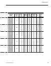
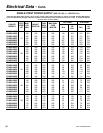
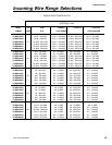
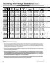
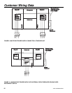
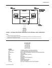
FIELD WIRING
All field wiring must comply with the National Electric
Code and all applicable local codes. YORK liquid chiller
units are factory wired for optimum reliability. Therefore
the unit controls must not be modified without expressed
written consent by YORK. The use of a simple switch or
timer from a remote point is permitted; but it must be
connected to the YORK unit panel at points expressly
indicated for that purpose.
Application Data