


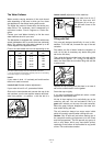
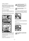
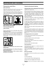
Water Outlet Connection
The end of the drain hose can be connected as
follows:
to the sink outlet siphon, securing it if necessary with
a clip;
to a wall outlet provided with vent-hole, minimum
internal diameter 4 cm;
hooked over the edge of the sink using the special
curved plastic guide provided.
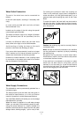
The waste connection must be at a height of between
30 cm (minimum) and 100 cm (maximum) from the
floor.
It makes no difference which way the drain hose
faces, either to the right or left of the dishwasher.
Avoid bending or kinking the hose as this could
prevent or slow down the discharge of water.
If you use a drain hose extension it must be no longer
than 2 metres and its internal diameter must be no
smaller than the diameter of the hose provided.
Likewise the internal diameter of the couplings used
for connection to the waste outlet must be no smaller
than the diameter of the drain hose.
Water Supply Connections
This dishwasher must be permanently plumbed into a
cold water supply.
The water pressure must be within the limits given in
the technical specifications, as it will not function
correctly if pressure is outside these specifications.
Your local Water Authority will advise you on the average
mains pressure in your area.
Where the water is supplied via a cold water storage
cistern, you can work out the pressure yourself by mea-
suring the vertical distance (or «head») between the
machine's inlet hose and the outlet from the cold water
storage cistern, allowing roughly 1 psi for every 2 feet.
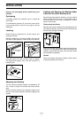
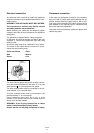
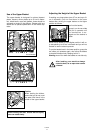
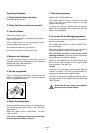
For making the connection itself, the coupling nut
fitted to the machine's supply hose is designed to
screw onto either a 3/4 inch gas thread spout, or to a
purpose made quick-coupling tap such as the Press
Block.
To make this easier, the hose itself may be turned to
the left or the right. In either case, be sure to incorpo-
rate the strainer (A) supplied with the machine into the
joint. See picture.
Caution: the retaining ring must be correctly fitted to
avoid water leaks.
Note: the end of the hose connected to the machine
can be positioned as required, by simply slackening
the retaining ring.
Re-tighten the ring securely to avoid water leaks.
Avoid bends or kinks in the hose which could prevent
or slow down the flow of water.
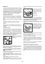
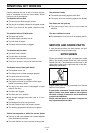
If the machine is connected to new pipes or pipes
which have not been used for a long time, you are
advised to run the water for a few minutes before
connecting the inlet hose. This will prevent deposits of
sand or rust clogging the inlet hose filter.
PIN17GB
5
A
CA04
CA06
Ø 21
Ø 18
Ø 18
Ø 21
min 30 cm
max 100 cm
max 100 cm
+ 2 m max
min 4 cm
CS12