


19
A: Removal Of Hob Top
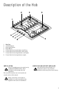
1. Remove all control knobs, pan supports, burner caps
and burner crowns.
2. Remove 2 screws for each burner.
3. Remove 4 fixing screws from the pan support hinges,
and remove the hinges from the hob.
4. Lift hob top at the rear and remove it from the hob.
B: Removal Of the Hob Taps
(Isolate Electrical Supply)
1. Follow the procedures in Section A.
2. Loosen the pipe connection nut from the gas tap with
the aid of a 16mm spanner.
3. From the underside of the hob remove 2 self tapping
screws from the tap.
4. Reassemble in reverse order and carry out leak test.
C: Removal Of Mains Terminal Block
(Isolate Electric Supply)
1. Follow the procedures in Section A.
2. Disconnect supply flex connections from terminal
block.
3. From the underside of the hob remove 1 self tapping
screw from the terminal block.
4. Reassemble in reverse order.
D: Removal Of Burner
1. Follow the procedures in Section A.
2. With the aid a 12mm spanner loosen off the pipe
connection nut.
3. From the underside of the hob remove 1 self tapping
screw from the burner body.
4. Reassemble in reverse order and carry out leak test.
E: Removal of Ignitor
(Isolate Electrical Supply)
1. Follow the procedures in Section A.
2. Remove H.T. leads from the ignitor by pulling tab
connection off. Disconnect supply cable from the
ignitor unit.
3. With the aid of a pair of thin nose pliers, pull the
spring clip sideward off of the underside of the
ignitor
4. Reassemble in reverse order.
F: Removal of Ignitor Switch
(Isolate Electric Supply)
1. Follow the procedures in Section A.
2. Disconnect the switches connector from the ignitor
unit and remove the supply cables pulling the tabs
connection off.
3. Reassemble in reverse order and check with wiring
diagram for correct reconnection.
Servicing
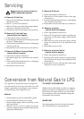
Conversion from Natural Gas to LPG
It is important to note that this model is designed for
use with natural gas but can be converted for use with
butane or propane gas providing the correct injectors
are fitted. The gas rate is adjusted to suit.
Method
• Ensure that the gas taps are in the 'OFF' position
• Isolate the hob from the electrical supply
• Remove all pan supports, burner caps, rings, crowns
and control knobs.
• With the aid of a 7mm box spanner the burner
injectors can then be unscrewed and replaced by the
appropriate LPG injectors.
TO ADJUST THE GAS RATE
With the aid of a thin bladed screwdriver completely
tighten down the by pass adjustment screw, which is
located down the centre of the gas tap control shaft.
Upon completion stick the replacement rating plate
on the under side of the hob.
IMPORTANT
The replacement/conversion of the gas hob should
only be undertaken by a competent person.
Repais may only be carried out by
CORGI registered engineers.