20 Getting Started Chapter 1
Setting Interrupt
Priority
Interrupts are enabled at power-up, after a SYSRESET, or after resetting the
module via the control register. An interrupt is generated after any channel
enable register is accessed when interrupts are enabled. The interrupt is
generated approximately 13 ms after one of the registers is accessed.
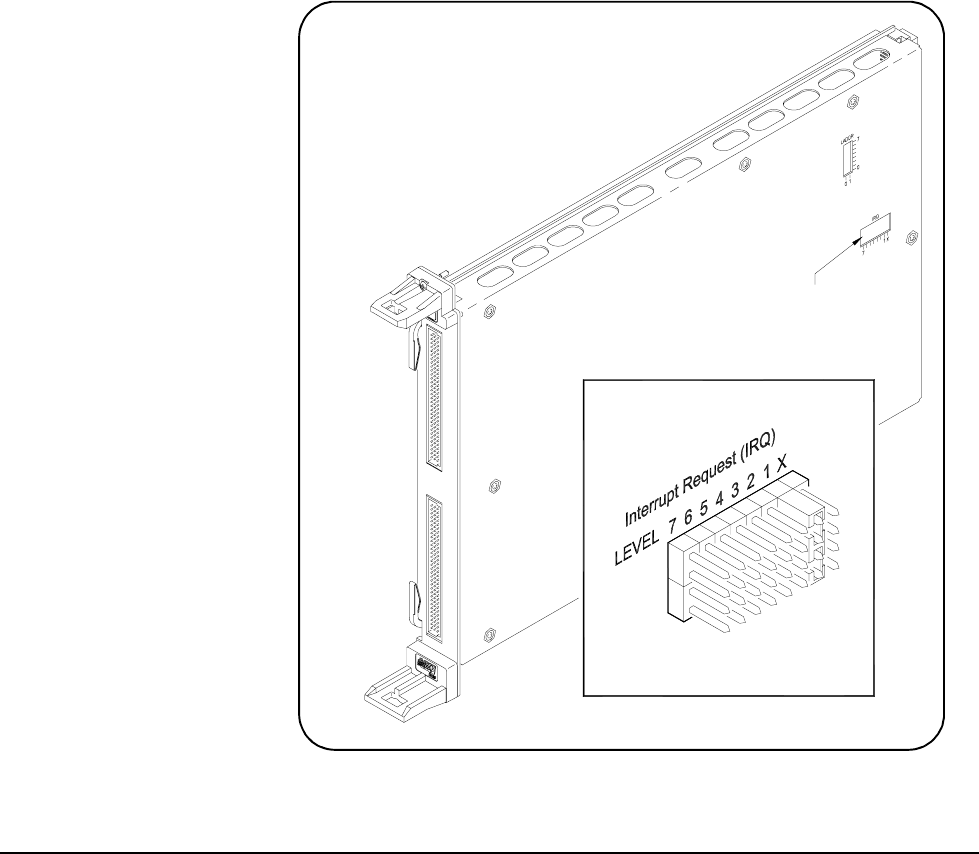
The interrupt priority jumper selects which priority level will be asserted.
The interrupt priority jumper is set in position 1 as shipped from the factory.
For most applications this priority level should not have to be changed.
The interrupts are disabled when set to level X. The interrupt priority jumpers
are identified on the sheet metal shield. A hole has been cut into it for
access. Interrupts can also be disabled using the Control Register. See
Figure 1-7 for Interrupt Request Level Jumper locations.
To change the setting, remove the jumper or jumpers from their current
position and place on the level you desire. If the card uses two 2-pin
jumpers, both jumpers must be placed in the same row for proper operation.
See the applicable mainframe manual to make sure backplane jumpers are
configured correctly.
Figure 1-7. Setting Interrupt Request (IRQ) Priority
LEVEL X = Interrupt Disabled
Request Level
Interrupt
Location
Jumper


