MIX 301 • Installation and Operation
MIX 301 • Installation and Operation
Installation and Operation, cont’d
6
7
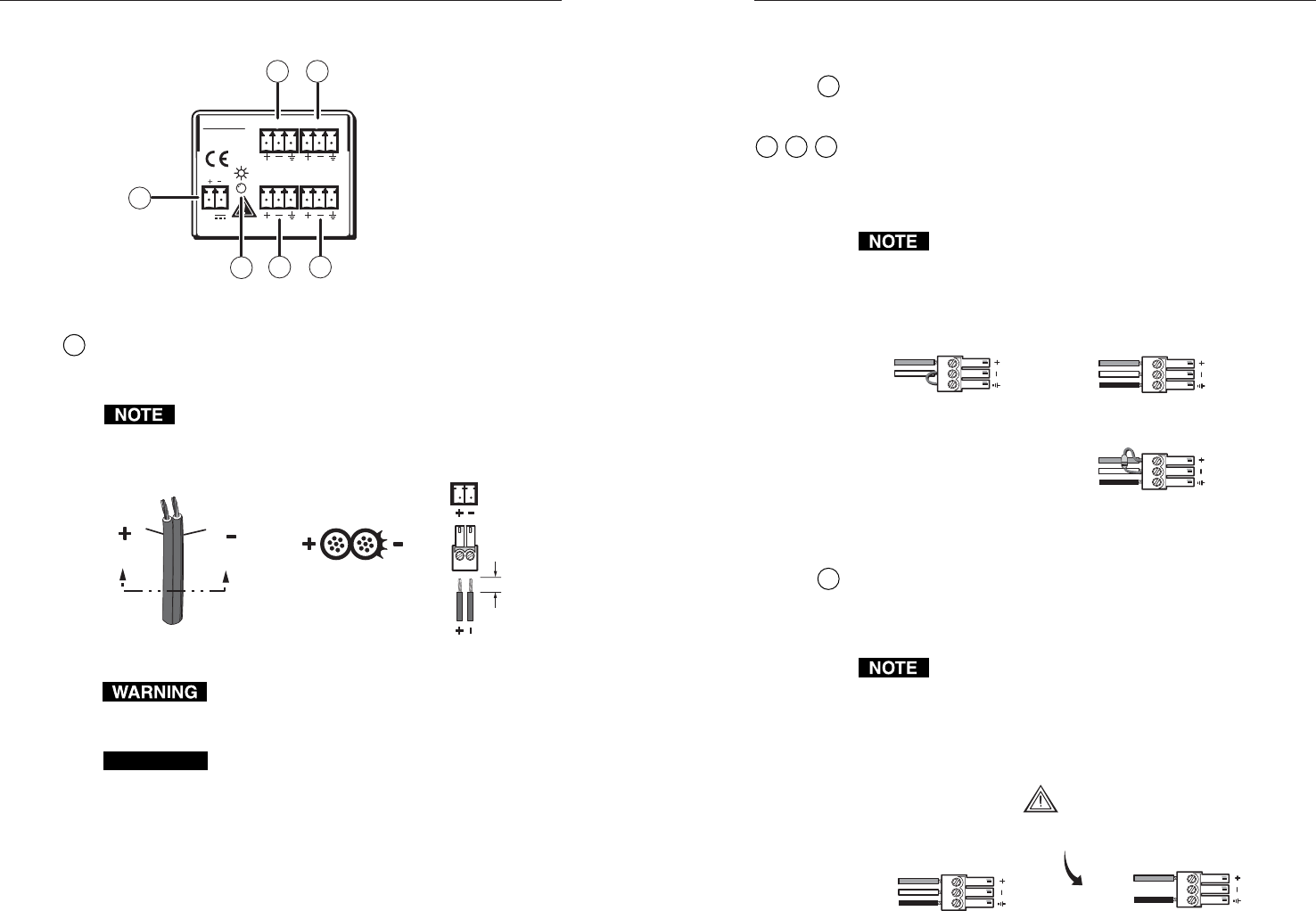
Rear Panel Features and Cabling
MIX 301
3 CHANNEL
MIXER
IN 2 MIX OUT
IN 1 IN 3
12V
0.5a
MAX
2
1
4 6
53
Figure 3 — MIX 301 rear panel
1
Captive screw power input connector — Connect the included
12 VDC external power supply into the 2-pole 3.5 mm captive
screw connector. Be careful to observe the correct polarity.
Do not tin the power supply leads before installing them
in the connector. Tinned wires are not as secure in the
connectors and could be pulled out.
Power Supply
Output Cord
Captive Screw
Connector
0.2” (5 mm) MAX
SECTION A–A
Ridges
Smooth
AA
The two power supply leads must be kept separated
while the power supply is plugged into an electrical
outlet. Remove power before wiring.
CAUTION
Power supply voltage polarity is critical. Incorrect
voltage polarity can damage the power supply and
the MIX 301. Identify the power cord negative lead
by the ridges on the side of the cord.
The length of the exposed (stripped) copper wires is
important. The ideal length is 0.2" (5 mm).
Longer bare wires can short together. Shorter
wires are not as secure in the direct insertion
connectors and could be pulled out.
To verify the polarity before connection, check the no load
power supply output with a voltmeter.
2
Power LED — Lights green to indicate that the MIX 301 has
power.
3
4
5
Balanced/unbalanced input connectors (IN 1, IN 2, IN 3) —
The balanced/unbalanced mono audio input is wired to a
3-pole, 3.5 mm captive screw connector. Wire the connector as
shown below.
Do not tin the connector leads before installing them in
the connector. Tinned wires are not as secure in the
connectors and could be pulled out. For further wiring
details, see the included “Cable Preparation For Audio
Connections” card.
600 ohm resistor
Tip
Sleeve
Ring
Tip
Sleeve
Ring
Tip
Sleeve
Unbalanced Input
(high impedance)
Left or Right
Left or Right
Balanced Input (high impedance)
Balanced Input (600 ohms)
6
Balanced output connector (MIX OUT) — The balanced mono
output is wired to a 3-pole, 3.5 mm captive screw connector.
Wire the connector as shown below for balanced or unbalanced
output devices.
Do not tin the connector leads before installing them in
the connector. Tinned wires are not as secure in the
connectors and could be pulled out. For further wiring
details, see the included “Cable Preparation For Audio
Connections” card.
Unbalanced Output (high impedance)
Tip
Sleeve
NO Ground Here
Tip
Sleeve
Ring
Balanced Output
CAUTION
For unbalanced audio, connect the sleeve(s)
to the ground. DO NOT connect the sleeve to
the negative (-) contact.


