2-14
PoleVault Systems Installation • Installation — Stage 2
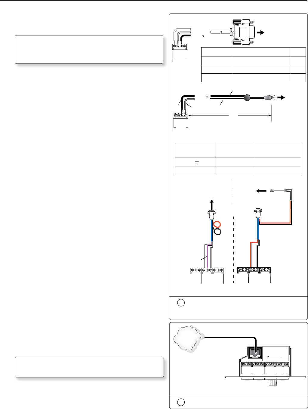
b. Connect the IR/RS-232 projector communication cable as
shown for either RS-232 or IR projector control.
N
Some projectors require NULL connection wiring,
which inverts the Tx and Rx connections. See the
projector manufacturer’s manual for details.
c. To use the MLC 104 IP Plus’s IP Link feature, connect a
network connected CAT 5, 5e, or 6 straight through cable
to the MLC’s RJ-45 LAN jack.
W
DO NOT connect the MLC’s RJ-45 LAN jack
to the PVS 305SA twisted pair inputs.
Connect the MLC to the projector with
an RS-232 cable or IR emitter cable, as
appropriate.
1
2
3
GROUND
+12 V OUT
CM
GROUND
IR OUT
GROUND
SCP
GROUND
Tx
Rx
DISPLAY
RS-232/IR
A B C D E
COMM LINK
LAN
PRESS TAB WITH
TWEEKER TO REMOVE
A B
MLS
RS-232
POWER
12V
DIGITAL
I/O
IR IN
Tx
GROUND
Rx
+12 V IN
MLC 104 IP Plus Right Side Panel
TCP/IP
Network
CAT 5, 5e or 6 Cable
Connect to the LAN using a CAT 5 cable
MLC 104 IP Plus
Right Side Panel
Ground ( )
Receive (Rx)
Tr ansmit (Tx)
GROUND
IR OUT
Tx
Rx
DISPLAY
RS-232/IR
RS-232 to projector
RS-232 connection
Terminal RS-232 Cable color Pin
Tx White 2
Rx Violet 3
Ground Shield 5
Terminal IR/RS-232
Cable color
IR Cable color
Ground
Black Black
IR Signal Red White/Black
+12V OUT
PWR SNS
GROUND
GROUND
GROUND
Tx
Rx
HOST/
CONFIG
PROJECTOR
RS-232/IR
Tx/IR
Rx
N White, Violet, an
Shield Not Used
Red
Black
Projector
MLC IR/RS-232
Comm Cable
IR Emitter
Connecting IR Cable
White
(or striped)
Black
Red
Black
9-Pin Female
White
Violet
Shield
+12V OUT
PWR SNS
GROUND
GROUND
GROUND
Tx
Rx
HOST/
CONFIG
PROJECTOR
RS-232/IR
Tx/IR
Rx
MLC 104 IP Plus
N Red and Black
Not Used
Connecting RS-232 Cable
Projector
MLC 104 IP Plus
Right Side Panel
To projector
Ground ( )
IR Signal
Unidirectional IR Output
via White Striped Wire
IR Emitter
100'
(30.5 m)
GROUND
IR OUT
Tx
Rx
DISPLAY
RS-232/IR
IR connection
Black
Black
Red


