GPS 400 Pilot’s Guide and Reference
190-00140-60 Rev. H
8-21
SECTION 8
AUX PAGES
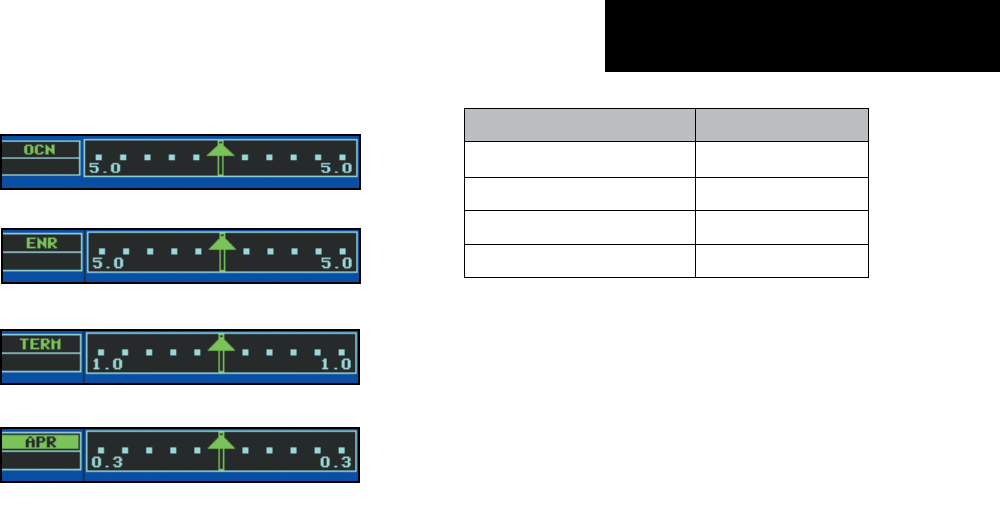
CDI Scales and Corresponding Flight Phases:
Oceanic
Enroute
Terminal
Approach
Figure 8-54 CDI Scales
During approach operations the CDI scale
gradually ramps down even further, to 0.3 nm.
This transition normally occurs within 2.0 nm of
the nal approach x (FAF). If a lower CDI scale
setting is selected (i.e., 1.0 nm or 0.3 nm) the
higher scale settings are not selected during any
phase of ight. For example, if 1.0 nm is selected,
the GPS 400 uses this for the enroute and
terminal phase and ramp down to 0.3 nm during
an approach. Note that the Receiver Autonomous
Integrity Monitoring (RAIM) protection limits
listed in Table 8-3 follow the selected CDI scale
and corresponding modes:
CDI Scale/Flight Phase: RAIM Protection:
Auto (oceanic) 4.0 nm
±
5.0 nm or Auto (enroute) 2.0 nm
±
1.0 nm or Auto (terminal) 1.0 nm
±
0.3 nm or Auto (approach) 0.3 nm
Table 8-3 CDI Scales
An arrival alarm, provided on the CDI/Alarms
Page, may be set to notify the pilot with a message
when the aircraft has reached a user-defined
distance to the final destination (the direct-to
waypoint or the last waypoint in a ight plan).
Once the aircraft has reached the set distance (up
to 99.9 units), an ‘Arrival at [waypoint]’ message
is displayed.
• ‘Units/Mag Var’ - Allows the pilot to congure
the displayed data to standard or metric units of
measure. This setting applies to distance, speed,
altitude, fuel, pressure, and temperature. Also
provides three magnetic variation (heading)
options: True, Auto, or User-dened. If ‘Auto’ is
selected, all track, course and heading information
is corrected to the magnetic variation computed
by the GPS receiver. The ‘True’ setting references
all information to true north, and the ‘User’ setting
corrects information to an user-entered value.


